Quantcast
Channel: Medium Voltage - Technical Articles | EEP - Electrical Engineering Portal
Viewing all 138 articles
Browse latest View live

Testing and Commissioning of Metal-Clad Switchgear

$
0
0
Distribution substation - 20/04kV MCset metal-clad switchgear  (Schneider Electric)

Distribution substation - 20/04kV MCset metal-clad switchgear (Schneider Electric)


Electrical testing and commissioning of Metal-Clad switchgear is essential to the safe start for the first time, regardless of its size, type or industry.

This article cover testing and start-up / commisioning procedures for all the components of medium voltage switchgear like circuit breaker, busbars, instrument transformers (current/voltage), disconnect and grounding switches etc.


1.1. Objective

To verify the physical condition and proper connections of bus bar.


1.2. Test Equipment Required:

• Insulation test (Megger)
• Micro ohmmeter
• High voltage tester
• Torque wrench


1.3. Test Procedure:

1.3.1. Mechanical Checks and Visual Inspection:

• Inspect switchgear and all components for any physical damage / defects.
• Check nameplate information for correctness.
• Inspect enclosures for proper alignment, foundation fixing, and grounding and vermin entry.
• Inspect all covers, panels’ section and doors for paintwork and proper fit.
• Check all the transport locks are removed.
• Check for smooth and proper movementof racking mechanisms, shutter, rollers, rails and guides.
• Check proper alignment of the primary and secondary contacts.
• Check operation of all mechanical interlocks.
• Check tightness of all bolted connections.
• Check for correct phasing connection of bus bar.
• Perform mechanical check and visual inspection for breaker / Contactor as per section.
• Perform mechanical check and visual inspection for instrument transformers as per section
• Perform mechanical check and visual inspection on all disconnect / grounding switches as per section.


1.3.2. Insulation Resistance Test:

It includes panel enclosure, busbar, CT and circuit breaker. The following precautions should be taken care, before starting the testing.

A visual inspection will be made to ensure the surface dust and moisture has been removed from the component under test. Ensure the component is isolated from other connected system, which may feed back to other components or circuits not under test.

On testing, voltage shall be applied between one phase and other phases connected with ground, testing shall be repeated for other phases as mentioned above. Test voltage limits mentioned in table below:

Rated voltageTest voltage
100-1000V AC/DC1000V DC
>1000 to <5000V AC2500V DC
> 5000V AC5000V DC

1.3.3. Contact Resistance Test:

This test is to confirm the busbar joints are connected properly and verify the tightness.

The test connection diagram is as shown in Figure below.

The test shall be done with CBs inserted and closed. Measure the contact dc resistance between panels by injecting 100A DC. This will include busbar joint, CB contact resistance, CB cluster resistance, and CT primary resistance (if applicable).

Limits:

The obtained results should be similar for all phases for each set of measurement. Other influencing factors to be considered, like length of the measured path, rating of the busbar, rating of CB, rating of CT and temperature.

Contact resistance test

Figure 1 - Contact resistance test

1.3.4 High Voltage Test

To determine the equipment is in propercondition to put in service, after installation for which it was designed and to give some basis for predicting whether or not that a healthy condition will remain or if deterioration is underway which can result in abnormally short life.


Test Instruments Required:

• Calibrated AC Hi-pot test set for switchgear with leakage current indicator and overload protection.
• Calibrated DC Hi-pot test set for cables with leakage current indicator and overload protection.


1.4. Applicable Standard

IEC60298: – AC metal enclosed switchgear and control gear for rated voltage above 1KV to 52KV.

Resource: Procedures for Testing and Commissioning of Electrical Equipment – Schneider Electric


Electrical Safety Standards for LV/MV/HV (Part-1)

$
0
0
Electrical Safety Standards for LV/MV/HV (Part-1)

Electrical Safety Standards for LV/MV/HV (on photo Indonesia's state energy giant - High Voltage Switchyard)

Content

  1. Standard: Western Power Company
  • Standard: New Zealand Electrical Code
  • Standard: ETSA Utilities
  • Standard: UK Power Networks – EI 02-0019
  • 1. Standard: Western Power Company

    Water Safely Clearance on Electrical Fires

    VoltageMinimum distances between a nozzle producing a fog stream of fresh water and a live conductor
    Up to 750 V1.5 Meter
    750 V to 15 KV4.0  Meter
    15 KV to 230 KV5.0 Meter

    Go to Content ↑


    Minimum Approach Distance for Authorized Person

    This is the minimum distance that must be maintained by a person, vehicle or mobile plant.

    VoltageDistance (minimum)
    Up to 1 KV0.7 Meter
    1 V to 6.6 KV0.7 Meter
    6.6 KV to 11 KV0.7 Meter
    11 KV to 22 KV0.7 Meter
    22 KV to 33 KV1.0 Meter
    33 KV to 66 KV1.0 Meter
    66 KV to 132 KV1.2 Meter
    132 KV to 220 KV1.8 Meter
    220 KV to 330 KV3.0 Meter

    Go to Content ↑


    Minimum Approach Distance for Ordinary Person

    VoltageDistance  (min)
    Up to 1 KV3.0 Meter
    1 V to 6.6 KV3.0 Meter
    6.6 KV to 11 KV3.0 Meter
    11 KV to 22 KV3.0 Meter
    22 KV to 33 KV3.0 Meter
    33 KV to 66 KV3.0 Meter
    66 KV to 132 KV3.0 Meter
    132 KV to 220 KV4.5 Meter
    220 KV to 330 KV6.0 Meter

    Go to Content ↑


    Minimum Approach Distance for Vehicle and Plant for Ordinary Person

    VoltageDistance  (min)
    Mobile PlantVehicle
    Up to 1 KV3.0 Meter0.6 Meter
    1 V to 6.6 KV3.0 Meter0.9 Meter
    6.6 KV to 11 KV3.0 Meter0.9 Meter
    11 KV to 22 KV3.0 Meter0.9 Meter
    22 KV to 33 KV3.0 Meter0.9 Meter
    33 KV to 66 KV3.0 Meter2.1 Meter
    66 KV to 132 KV3.0 Meter2.1 Meter
    132 KV to 220 KV3.0 Meter2.9 Meter
    220 KV to 330 KV6.0 Meter3.4 Meter

    Go to Content ↑

    2. Standard: New Zealand Electrical Code

    Min. Safe Distance between Buildings and Overhead Line

    VoltagePoleTower
    11 kV to 33 kV2 Meter2 Meter
    33 kV to 66 kV6 Meter6 Meter
    66 kV and Above8 Meter8 Meter

    Go to Content ↑


    Min. Safe Distance for excavation near Overhead Line

    Description of ClearanceFrom Pole (Min)From Tower (min)
    Excavation in land more than 750mm depth8 Meter12 Meter
    Excavation in land up to750mm depth2.2 to 5 Meter6 to12 Meter
    Excavation in land up to 300mm depth2.2 Meter6 Meter
    Construction near 11KV to 33KV Line2.2 Meter6 Meter
    Construction near 33KV to 66KV Line6 Meter9  Meter
    Construction near 66KV and more8 Meter12 Meter
    Wire Fence near 1KV to 66KV Line2.2 Meter2.2 Meter
    Wire Fence near 66KV and more5 Meter5 Meter

    Go to Content ↑


    Min. Safe Distance for Tower Carin near Electrical Tower

    Description of ClearanceDistance (Min)
    Mobile Carin movement4.0 Meter
    Tower Carin movement4.0 Meter
    Carin movement4.0 Meter
    Moving Activity above height of Tower4.0 Meter
    Hedge Cutter  movement4.0 Meter

    Go to Content ↑


    Min. Safe Vertical Distance above Railway Track

    Description of ClearanceDistance (Min)
    Earthed conductors5.5 Meter
    Stay wires5.5 Meter
    Conductors up to 33 kV6.5 Meter
    Conductors above 33 kV to 220 kV7.5 Meter
    Conductors above 220 kV.8 Meter

    Go to Content ↑


    Min. Distance between two Conductors on Same Supports

    High Voltage CircuitHigh Voltage CircuitDistance  between circuits (min)
    Up to 33 KVUp to 1KV1.0 Meter
    Up to 33 KVMore than 1KV1.2 Meter
    33 KV to 110 KVUp to 1KV1.5 Meter
    33 KV to 110 KVMore than 1KV2.0 Meter
    More than 110 KVAll2.5 Meter

    Go to Content ↑


    Min. Distance between two Conductors on Different Supports

    High Voltage CircuitDistance (min)
    Up to 1 KV0.6 Meter
    1 KV to 33 KV1.2 Meter
    33 KV to 66 KV1.8 Meter
    110 KV2.4 Meter
    More than 220 KV2.8 Meter

    Go to Content ↑


    Min. Safety Distance from Electrical Apparatuses

    Description of ClearanceDistance (min)
    Passage In front of Metal-Clad Switchgear (UP to HV)1.0 Meter wide 2.5 Height
    Passage In rear or side of Metal-Clad Switchgear (UP to HV)1.0 Meter wide 2.2 Height
    Passage at any side of Metal-Clad Switch gear containing Bare conductor (UP to HV)0.8 Meter wide 2.2 Height

    Go to Content ↑


    Min. Approach Distance for Non-Competent Person near exposed Live Parts

    VoltageDistance (min)
    Below 110 kV4.0 Meter
    220 kV and above6.0 Meter

    Go to Content ↑


    Min. Approach Distance for Competent Person near exposed Live Parts

    VoltageDistance (min)
    Below 1 kV0.5 Meter
    11 kV1.5 Meter
    22 kV2.0 Meter
    33 kV2.5 Meter
    66 kV3.0 Meter
    110 kV4.0 Meter
    220 kV and above6.0 Meter

    Go to Content ↑

    3. Standard: ETSA Utilities

    Vertical Clearances between Services

    ServiceLV CableHV Cable
    Common Pipe0.100 Meter0.100 Meter
    Gas Pipe0.200 Meter0.200 Meter
    Sewer Pipe0.300 Meter0.300 Meter
    Water Pipe0.600 Meter0.600 Meter

    Go to Content ↑


    Horizontal Clearances between Services

    ServiceLV CableHV Cable
    Common Pipe0.100 Meter0.100 Meter
    Gas Pipe0.200 Meter0.200 Meter
    Sewer Pipe1.0 Meter1.0 Meter
    Water Pipe0.600 Meter0.600 Meter

    Go to Content ↑

    4. Standard: UK Power Networks – EI 02-0019

    Cable Installation Depths

    VoltageAreaDepth (min)
    Low VoltageFootways, grass verges or private property0.450 Meter
    Carriageways (including road crossings)0.600 Meter
    Normal agricultural land (not deep ploughing)1.0 Meter
    Agricultural land subject to deep ploughing1.2 Meter
    11 KV to 20 KVFootways, grass verges or private property0.600 Meter
    Carriageways (including road crossings)0.750 Meter
    Normal agricultural land (not deep ploughing)1.0 Meter
    Agricultural land subject to deep ploughing1.2 Meter
    33 KV to 132 KVFootways, grass verges or private property0.9 Meter
    Carriageways (including road crossings)0.9 Meter
    Normal agricultural land (not deep ploughing)1.0 Meter
    Agricultural land subject to deep ploughing1.2 Meter
    Auxiliary Multi-core & Multi-pair CablesFootways, grass verges or private property0.450 Meter
    Carriageways (including road crossings)0.600 Meter
    Normal agricultural land (not deep ploughing)1.0 Meter
    Agricultural land subject to deep ploughing1.2 Meter
    On Cable Ladder for LV to HVThe Horizontal clearance between cables on cable ladders2X Dia of Cable of Largest Cable or min 150 mm
    The clearance from a supporting wall20 mm
    The vertical clearance between cables is greater150 mm
    If the number of cables > 4, they are to be installed in a horizontal

    Go to Content ↑


    Minimum Approach Distance of Crane or Moving Part from Live Conductor

    VoltageWithout Safety ObservationFor ordinary Person
    Un insulated portionsInsulated portions
    Up to 1KV2 Meter1.0 Meter3.0 Meter
    11 KV2 Meter1.4 Meter3.0 Meter
    22 KV2.4 Meter2 Meter3.0 Meter
    33 KV2.4 Meter2 Meter3.0 Meter
    66 KV2.8 Meter2 Meter3.0 Meter
    132 KV3.0 Meter3.0 Meter3.0 Meter
    220 KV4.8 Meter4.8 Meter6.0 Meter
    330 KV6.0 Meter6.0 Meter6.0 Meter
    500 KV8.0 Meter8.0 Meter8.0 Meter

    Go to Content ↑


    Minimum Fixed Clearances for Electrical Apparatus (Isolation Points)

    VoltageFixed Clearance
    Up to 11Kv0.320 Meter
    11KV to 33KV0.320 Meter
    33KV to 66KV0.630 Meter
    66KV to 132KV1.1 Meter

    Go to Content ↑

    Electrical Safety Standards for LV/MV/HV (Part-2)

    $
    0
    0
    Electrical Safety Standards for LV/MV/HV part 2

    Electrical Safety Standards for LV/MV/HV part 2 (on photo Downtown LA distribution power lines; photo by Hal Bergman Photography @Flickr)


    Continued from part 1Electrical Safety Standards for LV/MV/HV (Part-1)

    Content

    Standard: Northern Ireland Electricity (NIE), 6/025 ENA

    1. Clearances of Electrical Line to Ground and Roads
    2. Clearances of Electrical Line to Other Objects
    3. Clearances of Electrical Line to Trees and Hedges
    4. Clearances of Electrical Line to Street Lighting
    5. Clearances of Electrical Line to Waterways
    6. Clearances to Railways
    7. Clearances of Electrical Line to Fuel Tanks
    8. Clearances of Electrical Lines to other Electrical Lines
    9. Vertical Passing Clearance (sites where vehicles will pass below the lines)
    10. Horizontal Clearance (sites where there will be no work or passage of plant under lines)
    11. Distance between Conductors of Same/Different Circuit (On Same Support)
    12. Vertical Distance between Conductors of different Circuit (On Different Support)
    13. Distance between Conductors (Taken down from Pole to other Support, on Transformer)
    14. Horizontal Distance of Telecommunication Line & Overhead Line
    15. Passage Way for Metal-Clad Switchgear
    16. Safe approach distance for Person from Exposed Live Parts

    Standard: Northern Ireland Electricity (NIE), 6/025 ENA

    Clearances of Electrical Line to Ground and Roads

    Description of Clearance0.4 KV11 KV33KV110KV220 KV400KV
    Line conductor to any point not over road5.2 Meter6.1 Meter6.4 Meter6.4 Meter7.0 Meter7.0 Meter
    Line conductor to road surface5.8 Meter6.1 Meter6.4 Meter6.4 Meter7.4 Meter8.1 Meter
    Line conductor to road surface of high load routes6.9 Meter6.9 Meter6.9 Meter7.2 Meter8.5 Meter9.2 Meter
    Bare live metalwork ( transformer terminals, jumper connections, etc)4.6 Meter4.6 Meter4.6 Meter---

    Go to Content ↑


    Clearances of Electrical Line to Other Objects

    Description of Clearance<11 KV33 KV110KV220KV400 KV
    Line conductor or bare live metalwork to any object that is normally accessible (including permanently mounted ladders and access platforms) or to any surface of a building3.0 Meter3.0 Meter3.4 Meter4.6 Meter5.3 Meter
    Line conductor or bare live metalwork to any object to which access is not required AND on which a person cannot stand or lean a ladder0.8 Meter0.8 Meter1.2 Meter2.4 Meter3.1 Meter
    Line conductors to irrigates, slurry guns and high-pressure hoses30 Meter30 Meter30 Meter30 Meter30 Meter
    Line conductors to playing fields8.5 Meter8.5 Meter8.5 Meter8.5 Meter8.5 Meter
    Line conductors to Caravan Sites9.0 Meter9.0 Meter9.0 Meter9.0 Meter9.0 Meter
    Horizontal clearances to wells15.0 Meter15.0 Meter15.0 Meter15.0 Meter15.0 Meter

    Go to Content ↑


    Clearances of Electrical Line to Trees and Hedges

    Description of Clearance<11 KV33 KV110KV220KV400 KV
    Line conductor or bare live metalwork to trees or hedges unable to support a ladder or being climbed.0.8 Meter0.8 Meter1.2 Meter2.4 Meter3.1 Meter
    Line conductor or bare live metalwork to trees or hedges capable of supporting a ladder or being climbed.3.0 Meter3.0 Meter3.4 Meter4.6 Meter5.3 Meter
    Line conductor or bare live metalwork to trees falling towards the overhead line with the line conductors hanging vertically.0.8 Meter0.8 Meter1.2 Meter2.4 Meter3.1 Meter
    Line conductors to trees in Orchards3.0 Meter3.0 Meter3.4 Meter4.6 Meter5.3 Meter

    Go to Content ↑


    Clearances of Electrical Line to Street Lighting

    Description of Clearance0.4 KV11 KV33KV110KV220 KV400KV
    Line conductor to Lantern on same pole1.0 Meter-----
    Bare line conductor to lantern or column below.1.5 Meter-----
    Insulated line conductor to column0.3 Meter-----
    Insulated line conductor to lantern1.0 Meter-----
    Column to nearest LV pole1.5 Meter-----
    Line conductor to street lighting column with
    (1) Column in normal upright position.-1.7 Meter1.7 Meter2.3 Meter3.3 Meter4.0 Meter
    (2) Column falling towards line with line conductor hanging vertically only-1.7 Meter1.7 Meter2.3 Meter3.3 Meter4.0 Meter
    (3) Column falling towards line-0.4 Meter0.4 Meter0.8 Meter1.4 Meter1.9 Meter

    Go to Content ↑


    Clearances of Electrical Line to Waterways

    Description of Clearance0.4 KV11 KV33KV110KV220 KV400KV
    Navigable Waters: Lower bank to conductor or earth wire10.5 Meter10.5 Meter10.5 Meter10.5 Meter10.5 Meter10.5 Meter
    Minor Watercourses : Lower bank to conductor or earth wire7.6 Meter7.6 Meter7.6 Meter7.6 Meter7.6 Meter7.6 Meter

    Go to Content ↑


    Clearances to Railways

    Description of Clearance0.4 KV11 KV33KV110KV220 KV400KV
    Line conductor to ground level6.1 Meter6.1 Meter6.1 Meter6.7 Meter7.0 Meter7.6 Meter
    Line conductor to ground level on or across vehicle parks7.6 Meter8.5 Meter8.5 Meter9.1 Meter9.4 Meter10.1 Meter
    Line conductor to ground level at roads and yards, where road mobile cranes are likely to be employed10.7 Meter10.7 Meter10.7 Meter11.2 Meter11.5 Meter12.2 Meter
    Line conductor to Rail level7.3 Meter7.3 Meter7.3 Meter8.0 Meter8.2 Meter8.8 Meter
    Line conductor to the level of buildings, gantries or other structures (including those carrying traction wires) on which a man may be3.0 Meter3.0 Meter3.0 Meter3.7 Meter4.6 Meter6.1 Meter
    Line conductor to poles and other projections.2.4 Meter2.7 Meter2.7 Meter3.0 Meter3.7 Meter5.5 Meter
    Line conductor to any other wire other than traction wires.1.8 Meter1.8 Meter1.8 Meter2.4 Meter3.0 Meter3.7 Meter

    Go to Content ↑


    Clearances of Electrical Line to Fuel Tanks>

    Description of Clearance0.4 KV11 KV33KV110KV220 KV400KV
    Horizontal clearance from line conductors to petrol tanks and vents15 Meter15 Meter15 Meter15 Meter15 Meter15 Meter
    Horizontal clearance from line conductors to liquid gas tanks
    (1) 459 to 2273 litre capacity3.0 Meter3.0 Meter3.0 Meter3.4 Meter4.6 Meter5.3 Meter
    (2) 2274 to 9092 litre capacity7.6 Meter7.6 Meter7.6 Meter7.6 Meter7.6 Meter7.6 Meter
    (3) More than 9093 litre.15 Meter15 Meter15 Meter15 Meter15 Meter15 Meter
    Vertical clearance from line conductors to fuel oil tanks Please refer Clearances to Objects

    Go to Content ↑


    Clearances of Electrical Lines to other Electrical Lines

    Description of Clearance0.4 KV11 KV33KV110KV220 KV400KV
    Lowest line conductor or earth wire of upper line to highest line conductor of lower line.1.0 Meter1.8 Meter2.0 Meter2.5 Meter3.7 Meter4.4 Meter
    Lowest line conductor or earth wire of upper line to earth wire of lower line where erected.0.7 Meter1.4 Meter1.6 Meter2.5 Meter3.7 Meter4.4 Meter
    Lowest line conductor or earth wire of upper line to any point on a support of the lower line on which a person may stand.2.7 Meter2.8 Meter3.0 Meter3.4 Meter4.6 Meter5.3 Meter
    Support of upper line and any conductor of lower line.7.5 Meter7.5 Meter7.5 Meter15 Meter15 Meter15 Meter

    Go to Content ↑


    Vertical Passing Clearance (sites where vehicles will pass below the lines)

    Description of Clearance<33 KV110KV220KV400 KV
    Passing clearance: fixed height loads0.8 Meter1.4 Meter2.4 Meter3.1 Meter
    Passing Clearance: variable height loads.2.3 Meter3.2 Meter4.1 Meter5.0 Meter

    Go to Content ↑


    Horizontal Clearance (sites where there will be no work or passage of plant under lines)

    Description of Clearance<33 KV110KV220KV400 KV
    Minimum horizontal distances to safety barriers6.0 Meter9.0 Meter12.0 Meter14.0 Meter

    Go to Content ↑


    Distance between Conductors of Same/Different Circuit (On Same Support)

    Higher Voltage of either CircuitLower Voltage of either CircuitDistance between Circuits
    < 33 KV< 1 KV1.0 Meter
    < 33 KV> 1 KV1.2 Meter
    33 KV to 110 KV< 1 KV1.5 Meter
    33 KV to 110 KV> 1 KV2.0 Meter
    Above 110 KVAll2.5 Meter

    Go to Content ↑


    Vertical Distance between Conductors of different Circuit (On Different Support)

    Higher Voltage of either CircuitDistance between Circuits
    < 1 KV0.6 Meter
    1 KV to 33 KV1.2 Meter
    33 KV to 66 KV1.8 Meter
    110 KV2.4 Meter
    220 KV2.8 Meter

    Go to Content ↑


    Distance between Conductors (Taken down from Pole to other Support, on Transformer)

    VoltageDistance between Circuits
    11 KV & LV Line0.60 Meter
    22 KV & LV Line0.75 Meter
    33 KV & LV Line0.90 Meter

    Go to Content ↑


    Horizontal Distance of Telecommunication Line & Overhead Line

    Description of ClearanceDistance
    Telecommunication Line(Not insulated) to HV LineMin 1.6 Meter
    Telecommunication Line (Bare) to LV (Bare) LineMin 1.2 Meter
    Telecommunication Line (Covered) to LV (Bare) LineMin 0.6 Meter
    Telecommunication Line (Bare) to Stay (Bare) WireMin 0.3 Meter

    Go to Content ↑


    Passage Way for Metal-Clad Switchgear

    Description of ClearanceDistance
    Clean &unobstructed Passages at the front of any Low/High Voltage Switchgear.1.0 Meter wide & 2.5 Meter high
    Clean &unobstructed Passages at side or under any earthed enclosure containing Bare Conductor0.8 Meter wide & 2.2 Meter high

    Go to Content ↑


    Safe approach distance for Person from Exposed Live Parts

    Circuit VoltageDistance
    < 1 KV0.5 Meter
    11 KV1.5 Meter
    22 KV2.0 Meter
    33 KV2.5 Meter
    66 KV3.0 Meter
    110 KV4.0 Meter
    >220 KV6.0 Meter

    Go to Content ↑

    Electrical Safety Standards for LV/MV/HV (Part-3)

    $
    0
    0
    Electrical Safety Standards for LV/MV/HV part 3

    Electrical Safety Standards for LV/MV/HV part 3 (On photo transmission tower in India)


    Continued from part 2Electrical Safety Standards for LV/MV/HV (Part-2)

    Content

    Standard: Northern Ireland Electricity (NIE), 6/025 ENA

    Code: Indian Electricity Rules / Central Electricity Authority

    1. Right of Way Clearance (As per GETCO Standard)
    2. Minimum clearances between Electrical Lines crossing each other
    3. Permissible Min ground Clearance of Electrical Line
    4. Clearance for Telephone line Crossings Power Line
    5. Vertical Clearance between Electrical Line and railway tracks
    6. Clearance from Buildings to low, medium & high voltage lines
    7. Clearance above ground at the lowest conductor
    8. Vertical Clearance at Middle of Span
    9. Safety Clearance from Live Part in Outdoor Substation
    10. Lying of Telecommunication Cables with Power Cables (>33 kV)
    11. Safe approach limits for people

    Code: Indian Electricity Rules / Central Electricity Authority

    Right of Way Clearance (As per GETCO Standard)

    KVMin ROW
    66 KV18 Meter
    132 KV27 Meter
    220 KV35 Meter
    400KV52 Meter (Single Circuit)
    400 KV48 Meter (Double Circuit)

    Go to Content ↑


    Minimum clearances between Electrical Lines crossing each other

    Voltage66 KV132 KV220 KV400 KV
    66 KV2.4 Meter3 Meter4.5 Meter5.4 Meter
    132 KV3 Meter3 Meter4.5 Meter5.4 Meter
    220 KV4.5 Meter4.5 Meter4.5 Meter5.4 Meter
    400 KV4.5 Meter5.4 Meter5.4 Meter5.4 Meter

    Go to Content ↑


    Permissible Min ground Clearance of Electrical Line

    KVGround ClearanceOver National Highway
    66 KV6.1 Meter8.0 Meter
    132 KV6.1 Meter8.6 Meter
    220 KV7.0 Meter9.8 Meter
    400KV8.8 Meter10.8 Meter

    Go to Content ↑


    Clearance for Telephone line Crossings Power Line

    KVClearance (Min)
    66 KV2.4 Meter
    132 KV2.7 Meter
    220 KV3.0 Meter

    Go to Content ↑


    Vertical Clearance between Electrical Line and railway tracks

    KVClearance (Min)
    66 KV14 Meter
    132 KV14.6 Meter
    220 KV15.4 Meter
    400 KV17.9 Meter

    Go to Content ↑


    Clearance from Buildings to low, medium and high voltage lines

    VoltageDescriptionDistance
    Low & Medium VoltageFlat roof, open balcony, verandah roof ,When the line passes above the building a vertical clearance from the highest point2.5 Meter
    Low & Medium VoltageLine passes adjacent to the building a horizontal clearance from the nearest point1.2 Meter
    Low & Medium VoltageLine passes above the building a vertical clearance2.5 Meter
    Low & Medium VoltageLine passes adjacent the building a Horizontal clearance1.2 Meter
    11 KV to 33 KVLine passes above or adjacent   to any building or part of a building3.7  Meter
    Above 33 KVLine passes above or adjacent   to any building or part of a building3.7+(0.3 for every additional 33 KV )
    Up to 11 KVThe horizontal clearance between the nearer conductor and any part of such building1.2 Meter
    11 KV to 33 KVThe horizontal clearance between the nearer conductor and any part of such building2.0 Meter
    Above 33 KVThe horizontal clearance between the nearer conductor and any part ofsuch building2.0 + (0.3 for every additional 33 KV )

    Go to Content ↑


    Clearance above ground at the lowest conductor

    VoltageDescriptionDistance
    Low & Medium VoltageAcross a street5.8 Meter
    High VoltageAcross a street6.1 Meter
    Low & Medium VoltageAlong a street5.5 Meter
    High VoltageAlong a street5.8 Meter
    Low & Medium VoltageElsewhere than along or across any street4.0 Meter
    High VoltageElsewhere than along or across any street5.2 Meter
    33 KV & EHVClearance above ground(Add 0.3 Meter for every 33 KV Volts in 5.2 Meter)Min 6.1 Meter

    Go to Content ↑


    Vertical Clearance at Middle of Span

    SpanVertical Clearance (At Middle of Span)
    200 Meter4.0 Meter
    300 Meter5.5 Meter
    400 Meter7.0 Meter
    500 Meter8.5 Meter

    Go to Content ↑


    Safety Clearance from Live Part in Outdoor Substation

    KVSafety Working Clearance
    12 KV2.6 Meter
    36 KV2.8 Meter
    72.5 KV3.1 Meter
    145 KV3.7 Meter
    220 KV4.3 Meter
    400KV6.4 Meter
    800 KV10.3 Meter

    Go to Content ↑


    Lying of Telecommunication Cables with Power Cables (>33 kV)

    CableMin. Distance
    Power cable of voltage exceeding 33 kV shall be laidMin 1.2 Meter depth
    Underground telecommunication cable shall be with underground power cable of voltage exceeding 33 kV.Min 0.6 Meter Separate from Power Cable

    Go to Content ↑


    Safe approach limits for people

    Voltage214V to 415 KV11KV33KV66KV132KV275KV
    Person using manually operated tool1.3 Meter2.0 Meter3.0 Meter4.0 Meter5.0 Meter6.0 Meter
    Person using power operated tool3.0 Meter3.0 Meter3.0 Meter4.0 Meter5.0 Meter6.0 Meter

    Go to Content ↑

    Arrangements of LV Utility Distribution Networks (1)

    $
    0
    0
    Arrangements of LV Utility Distribution Networks

    Arrangements of LV Utility Distribution Networks (photo credit to abbmvit.blogspot.com)

    Introduction

    In European countries the standard 3-phase 4-wire distribution voltage level is 230/400 V. Many countries are currently converting their LV systems to the latest IEC standard of 230/400 V nominal (IEC 60038).

    Medium to large-sized towns and cities have underground cable distribution systems.

    MV/LV distribution substations, mutually spaced at approximately 500-600 metres, are typically equipped with:

    1. A 3-or 4-way MV switchboard, often made up of incoming and outgoing load-break switches forming part of a ring main, and one or two MV circuit-breakers or combined fuse/ load-break switches for the transformer circuits
    2. One or two 1,000 kVA MV/LV transformers
    3. One or two (coupled) 6-or 8-way LV 3-phase 4-wire distribution fuse boards, or moulded-case circuit-breaker boards, control and protect outgoing 4-core distribution cables, generally referred to as “distributors

    The output from a transformer is connected to the LV busbars via a load-break switch, or simply through isolating links. In densely-loaded areas, a standard size of distributor is laid to form a network, with (generally) one cable along each pavement and 4-way link boxes located in manholes at street corners, where two cables cross.

    Recent trends are towards weather-proof cabinets above ground level, either against a wall, or where possible, flush-mounted in the wall. Links are inserted in such a way that distributors form radial circuits from the substation with open-ended branches (see Fig. C3).

    Where a link box unites a distributor from one substation with that from a neighbouring substation, the phase links are omitted or replaced by fuses, but the neutral link remains in place.

    Showing one of several ways in which a LV distribution network may be arranged

    Fig. C3 : Showing one of several ways in which a LV distribution network may be arranged for radial branched-distributor operation, by removing (phase) links


    This arrangement provides a very flexible system in which a complete substation can be taken out of service, while the area normally supplied from it is fed from link boxes of the surrounding substations.

    Moreover, short lengths of distributor (between two link boxes) can be isolated for fault-location and repair. Where the load density requires it, the substations are more closely spaced, and transformers up to 1,500 kVA are sometimes necessary.

    Other forms of urban LV network, based on free-standing LV distribution pillars, placed above ground at strategic points in the network, are widely used in areas of lower load density. This scheme exploits the principle of tapered radial distributors in which the distribution cable conductor size is reduced as the number of consumers downstream diminish with distance from the substation.

    In this scheme a number of large-sectioned LV radial feeders from the distribution board in the substation supply the busbars of a distribution pillar, from which smaller distributors supply consumers immediately surrounding the pillar.

    Distribution in market towns, villages and rural areas generally has, for many years, been based on bare copper conductors supported on wooden, concrete or steel poles, and supplied from pole-mounted or ground-mounted transformers.

    In recent years, LV insulated conductors, twisted to form a two-core or 4-core self supporting cable for overhead use, have been developed, and are considered to be safer and visually more acceptable than bare copper lines. This is particularly so when the conductors are fixed to walls (e.g. under-eaves wiring) where they are hardly noticeable.

    Improved methods using insulated twisted conductors to form a pole mounted aerial cable are now standard practice in many countriesAs a matter of interest, similar principles have been applied at higher voltages, and self supporting “bundled” insulated conductors for MV overhead installations are now available for operation at 24 kV. Where more than one substation supplies a village, arrangements are made at poles on which the LV lines from different substations meet, to interconnect corresponding phases.

    North and Central American practice differs fundamentally from that in Europe, in that LV networks are practically nonexistent, and 3-phase supplies to premises in residential areas are rare.

    The distribution is effectively carried out at medium voltage in a way, which again differs from standard European practices.

    The MV system is, in fact, a 3-phase 4-wire system from which single-phase distribution networks (phase and neutral conductors) supply numerous single-phase transformers, the secondary windings of which are centre-tapped to produce 120/240 V single-phase 3-wire supplies.

    In Europe, each utility-supply distribution substation is able to supply at LV an area corresponding to a radius of approximately 300 metres from the substation. North and Central American systems of distribution consist of a MV network from which numerous (small) MV/LV transformers each supply one or several consumers, by direct service cable (or line) from the transformer location

    The central conductors provide the LV neutrals, which, together with the MV neutral conductors, are solidly earthed at intervals along their lengths. Each MV/LV transformer normally supplies one or several premises directly from the transformer position by radial service cable(s) or by overhead line(s).

    Many other systems exist in these countries, but the one described appears to be the most common. Figure C4 (in next part…) shows the main features of the two systems.

    Will be continued…

    Resource: Electrical Installation Guide 2009 – Schneider Electric

    Arrangements of LV Utility Distribution Networks (2)

    $
    0
    0
    Arrangements of LV Utility Distribution Networks

    Arrangements of LV Utility Distribution Networks (photo by Steve Ives @ Flickr: Street in Haddington, Philadelphia, PA, US)


    Continued from the previous part: Arrangements of LV Utility Distribution Networks (1)


    The consumer-service connection

    In the past, an underground cable service or the wall-mounted insulated conductors from an overhead line service, invariably terminated inside the consumer’s premises, where the cable-end sealing box, the utility fuses (inaccessible to the consumer) and meters were installed.

    A more recent trend is (as far as possible) to locate these service components in a weatherproof housing outside the building.

    Widely-used American and European-type systems

    Fig. C4: Widely-used American and European-type systems


    Note: At primary voltages greater than 72.5 kV in bulk-supply substations, it is common practice in some European countries to use an earthed-star primary winding and a delta secondary winding. The neutral point on the secondaryside is then provided by a zigzag earthing reactor,the star point of which is connected to earth through a resistor. 

    Frequently, the earthing reactor has a secondary winding to provide LV3-phase supplies for the substation. It is then referred to as an “earthing transformer”.

    A MCCB  - moulded case circuit breaker which incorporates a sensitive residual-current earth-fault protective feature is mandatory at the origin of any LV installation forming part of a TT earthing system.

    The utility/consumer interface is often at the outgoing terminals of the meter(s) or, in some cases, at the outgoing terminals of the installation main circuit-breaker (depending on local practices) to which connection is made by utility staff, following a satisfactory test and inspection of the installation.

    A typical arrangement is shown in Figure C5.

    Typical service arrangement for TT-earthed systems

    Fig. C5: Typical service arrangement for TT-earthed systems


    A further reason for this MCCB is that the consumer cannot exceed his (contractualdeclared maximum load, since the overload trip setting, which is sealed by the supply authority, will cut off supply above the declared value. Closing and tripping of the MCCB is freely available to the consumer, so that if the MCCB is inadvertently tripped on overload, or due to an appliance fault, supplies can be quickly restored following correction of the anomaly.

    In view of the inconvenience to both the meter reader and consumer, the location of meters is nowadays generally outside the premises, either:

    • In a free-standing pillar-type housing as shown in Figures C6 and C7
    • In a space inside a building, but with cable termination and supply authority’s fuses located in a flush-mounted weatherproof cabinet accessible from the public way, as shown in Figure C8
    • For private residential consumers, the equipment shown in the cabinet in.
    Typical rural-type installation

    Fig. C6 : Typical rural-type installation


    In this kind of installation it is often necessary to place the main installation circuit-breaker some distance from the point of utilization, e.g. saw-mills, pumping stations,  etc.


    Semi-urban installations (shopping precincts, etc.)

    Fig. C7: Semi-urban installations (shopping precincts, etc.)


    The main installation CB is located in the consumer’s premises in cases where it is  set to trip if the declared kVA load demand is exceeded.


    Town centre installations

    Fig. C8: Town centre installations


    The service cable terminates in a flushmounted wall cabinet which contains the  isolating fuse links, accessible from the public way. This method is preferred for  esthetic reasons, when the consumer can provide a suitable metering and main-switch location.


    Typical LV service arrangement for residential consumers

    Fig. C9: Typical LV service arrangement for residential consumers


    Figure C5 is installed in a weatherproof cabinet mounted vertically on a metal frame in the front garden, or flush mounted in the boundary wall, and accessible to authorized personnel from the pavement.

    Figure C9 shows the general arrangement, in which removable fuse links provide the means of isolation.

    In the field of electronic metering, techniques have developed which make their use attractive by utilities either for electricity metering and for billing purposes, the liberalisation of the electricity market having increased the needs for more data collection to be returned from the meters.

    For example electronic metering can also help utilities to understand their customers’ consumption profiles.

    In the same way, they will be useful for more and more power line communication and radio-frequency applications as well.

    In this area, prepayment systems are also more and more employed when economically justified. They are based on the fact that for instance consumers having made their payment at vending stations, generate tokens to pass the information concerning this payment on to the meters. For these systems the key issues are security and inter-operability which seem to have been addressed successfully now.

    The attractiveness of these systems is due to the fact they not only replace the meters but also the billing systems, the reading of meters and the administration of the revenue collection.

    Resource: Electrical Installation Guide 2009 – Schneider Electric

    Differences Between Earthed and Unearthed Cables

    $
    0
    0
    Differences Between Earthed and Unearthed Cables

    Differences Between Earthed and Unearthed Cables

    Introduction

    In HT electrical distribution, the system can be earthed or unearthed.

    The selection of unearthed or earthed cable depends on distribution system. If such system is earthed, then we have to use cable which is manufactured for earthed system. (which the specifies the manufacturer). If the system is unearthed then we need to use cable which is manufactured for unearthed system.

    The unearthed system requires high insulation level compared to earthed system.

    For earthed and unearthed XLPE cables, the IS 7098 part2 1985 does not give any difference in specification. The insulation level for cable for unearthed system has to be more.


    Earthed System

    Earlier the generators and transformers were of small capacities and hence the fault current was less. The star point was solidly grounded. This is called earthed system.

    In three phases earthed system, phase to earth voltage is 1.732 times less than phase to phase voltage. Therefore voltage stress on cable to armor is 1.732 times less than voltage stress between conductors to conductor.

    Where in unearthed system, (if system neutral is not grounded) phase to ground voltage can be equal to phase to phase voltage. In such case the insulation level of conductor to armor should be equal to insulation level of conductor to conductor.

    In an earthed cable, the three phase of cable are earthed to a ground. Each of the phases of system is grounded to earth.

    Example: 1.9/3.3 KV, 3.8/6.6 KV system


    Unearthed System

    Today generators of 500MVA capacities are used and therefore the fault level has increased. In case of an earth fault, heavy current flows into the fault and this lead to damage of generators and transformers. To reduce the fault current, the star point is connected to earth through a resistance. If an earth fault occurs on one phase, the voltage of the faulty phase with respect to earth appears across the resistance.

    Therefore, the voltage of the other two healthy phases with respect to earth rises by 1.7 times.

    If the insulation of these phases is not designed for these increased voltages, they may develop earth fault. This is called unearthed system.

    In an unearth system, the phases are not grounded to earth .As a result of which there are chances of getting shock by personnel who are operating it.

    Example: 6.6/6.6 KV, 3.3/3.3 KV system.

    Unearthed cable has more insulation strength as compared to earthed cable. When fault occur phase to ground voltage is √3 time the normal phase to ground voltage. So if we used earthed cable in unearthed System, It may be chances of insulation puncture.

    So unearthed cable are used. Such type of cable is used in 6.6 KV systems where resistance type earthing is used.

    Nomenclature

    In simple logic the 11 KV earthed cable is suitable for use in 6.6 KV unearthed system. The process of manufacture of cable is same.

    The size of cable will depend on current rating and voltage level.

    • Voltage Grade (Uo/U) where Uo is Phase to Earth Voltage & U is Phase to Phase Voltage.
    • Earthed system has insulation grade of KV / 1.75 x KV.
    • For Earthed System (Uo/U): 1.9/3.3 kV, 3.8/6.6 kV, 6.35/11 kV, 12.7/22 kV and 19/33 kV.
    • Unearthed system has insulation grade of KV / KV.
    • For Unearthed System (Uo/U): 3.3/3.3 kV and 11/11 kV.
    • 3 phase 3 wire system has normally Unearthed grade cables and 3 phase 4 wire systems can be used earthed grade cables, insulation used is less, and cost is less.

    Thumb Rule

    As a thumb rule we can say that 6.6KV unearthed cable is equal to 11k earthed cable i.e 6.6/6.6kv Unearthed cable can be used for 6.6/11kv earthed system.

    Because each core of cable have the insulation level to withstand 6.6kv so between core to core insulation level will be 6.6kV+6.6kV = 11kV

    For transmission of HT, earthed cable will be more economical due to low cost where as unearthed cables are not economical but insulation will be good.

    Generally 6.6 kV and 11kV systems are earthed through a neutral grounding resistor and the shield and armor are also earthed, especially in industrial power distribution applications.  Such a case is similar to an unearthed application but with earthed shield (sometimes called solid bonding).

    In such cases, unearthed cables may be used so that the core insulation will have enough strength but current rating is de-rated to the value of earthed cables.

    But it is always better to mention the type of system earthing in the cable specification when ordering the cables so that the cable manufacturer will take care of insulation strength and de rating.

    Medium Voltage Switchgear (1) – Basics of Switching Devices

    $
    0
    0
    Medium Voltage Switchgear (1) – Basics of Switching Devices

    Medium Voltage Switchgear (1) – Basics of Switching Devices

    Introduction to Medium Voltage

    According to international rules, there are only two voltage levels:

    1. Low voltage: up to and including 1kV AC (or 1,500V DC).
    2. High voltage: above 1kV AC (or 1,500V DC).

    Most electrical appliances used in household, commercial and industrial applications work with low voltage. High voltage is used not only to transmit electrical energy over very large distances, but also for regional distribution to the load centers via fine branches.

    However, because different high voltage levels are used for transmission and regional distribution, and because the tasks and requirements of the switchgear and substations are also very different, the term ‘medium voltage’ has come to be used for the voltages required for regional power distribution that are part of the high voltage range from 1kV AC up to and including 52kV AC.

    Most operating voltages in medium voltage systems are in the 3kV AC to 40.5kV AC range.

    The electrical transmission and distribution systems not only connect power stations and electricity consumers, but also, with their ‘meshed systems’, form a supraregional backbone with reserves for reliable supply and for the compensation of load differences.

    High operating voltages (and therefore low currents) are preferred for power transmission in order to minimize losses. The voltage is not transformed to the usual values of the low voltage system until it reaches the load centers close to the consumer.

    In public power supplies, the majority of medium voltage systems are operated in the 10kV to 30kV range (operating voltage). The values vary greatly from country to country, depending on the historical development of technology and the local conditions.


    1. Medium voltage equipment

    Apart from the public supply, there are still other voltages fulfilling the needs of consumers in industrial plants with medium voltage systems; in most cases, the operating voltages of the motors installed are decisive.

    Operating voltages between 3kV and 15kV are frequently found in industrial supply systems.

    In power supply and distribution systems, medium voltage equipment is available in:

    1. Power stations, for generators and station supply systems.
    2. Transformer substations of the primary distribution level (public supply system or systems of large industrial companies), in which power supplied from the high voltage system is transformed to medium voltage.
    3. Local supply, transformer or customer transfer substations for large consumers (secondary distribution level), in which the power is transformed from medium to low voltage and distributed to the consumer.
    Power distribution network scheme

    Power distribution network scheme

    2. Basics of Switching Devices

    Switching devices are devices used to close (make) or open (break) electrical circuits.

    The following stress can occur during making and breaking:

    • No-load switching
    • Breaking of operating currents
    • Breaking of short circuit currents

    What can the different switching devices do?

    Circuit breakers:

    Make and break all currents within the scope of their ratings, from small inductive and capacitive load currents up to the full short circuit current, and this under all fault conditions in the power supply system, such as earth faults, phase opposition, and so on.

    Switches:

    Switch currents up to their rated normal current and make on existing short circuits (up to their rated short circuit making current).

    Disconnectors (isolators):

    Used for no-load closing and opening operation. Their function is to isolate ‘downstream’ devices so they can be worked on.

    Three-position disconnectors:

    Combine the functions of disconnecting and earthing in one device. Three-position disconnectors are typical for GIS – Gas insulated switchgear.

    Switch disconnectors (load break switches):

    The combination of a switch and a disconnector, or a switch with isolating distance.

    Contactors:

    Load breaking devices with a limited short circuit making or breaking capacity. They are used for high switching rates.

    Earthing switches:

    To earth isolated circuits.

    Make-proof earthing switches (earthing switches with making capacity):

    Are used for the safe earthing of circuits, even if voltage is present, that is, also in the event that the circuit to be earthed was accidentally not isolated.

    Fuses:

    Consist of a fuse base and a fuse link. With the fuse base, an isolating distance can be established when the fuse link is pulled out in de-energized condition (like in a disconnector). The fuse link is used for one single breaking of a short circuit current.

    Surge arresters:

    To discharge loads caused by lightning strikes (external overvoltages) or switching operations and earth faults (internal overvoltages). They protect the connected equipment against impermissibly high voltages.

    Will be continued very soon…

    References: SIEMENS Power Engineerind Guide – ‘Switchgear and Substations’


    Medium Voltage Switchgear (2) – Selection of Switching Devices

    $
    0
    0
    Medium Voltage Switchgear (2) – Selection of Switching Devices

    Medium Voltage Switchgear (2) – Selection of Switching Devices


    Continued from first part: Medium Voltage Switchgear (1) – Basics of Switching Devices


    3. Selection of Switching Devices

    Switching devices are selected both according to their ratings and according to the switching duties to be performed, which also includes the switching rates.

    1. Selection according to ratings
    2. Selection according to endurance and switching rates
      1. Switches (general, sf6, air-break, vacuum)
      2. Circuit Breakers
      3. Disconnectors
      4. Earthing Switches
      5. Contactors

    3.1 Selection according to ratings

    The system conditions, that is, the properties of the primary circuit, determine the required parameters.

    The most important of these are:

    Rated voltage

    The upper limit of the system voltage the device is designed for. Because all high voltage switching devices are zero-current interrupters, except for some for fuses the system voltage is the most important dimensioning criterion.

    It determines the dielectric stress of the switching device by means of the transient recovery voltage and the recovery voltage, especially while switching off.

    Rated insulation level

    The dielectric strength from phase to earth, between phases and across the open contact gap, or across the isolating distance. The dielectric strength is the capability of an electrical component to withstand all voltages with a specific time sequence up to the magnitude of the corresponding withstand voltages.

    These can be operating voltages or higher frequency voltages caused by switching operations, earth faults (internal overvoltages) or lightning strikes (external overvoltages). The dielectric strength is verified by a lightning impulse withstand voltage test with the standard impulse wave of 1.2/50μs and a power frequency withstand voltage test (50Hz/1min).

    Rated normal current

    The current that the main circuit of a device can continuously carry under defined conditions. The temperature increase of components – especially contacts must not exceed defined values.

    Permissible temperature increases always refer to the ambient air temperature. If a device is mounted in an enclosure, it may be advisable to load it below its full rated current, depending on the quality of heat dissipation.

    Rated peak withstand current

    The peak value of the major loop of the short circuit current during a compensation process after the beginning of the current flow, which the device can carry in closed state.

    It is a measure for the electrodynamic (mechanical) load of an electrical component. For devices with full making capacity, this value is not relevant.

    Rated short circuit making current

    The peak value of the making current in case of short circuit at the terminals of the switching device. This stress is greater than that of the rated peak withstand current, because dynamic forces may work against the contact movement.

    Rated breaking current

    The load breaking current in normal operation. For devices with full breaking capacity and without a critical current range, this value is not relevant.

    Rated short circuit breaking current

    The root – mean – square value of the breaking current in case of short circuit at the terminals of the switching device.


    3.2 Selection according to endurance and switching rates

    If several devices satisfy the electrical requirements and no additional criteria have to be taken into account, the required switching rate can be used as an additional selection criterion.

    Table 1 through table 5 show the endurance of the switching devices, providing a recommendation for their appropriate use. The respective device standards distinguish between classes of mechanical (M) and electrical (E) endurance, whereby they can also be used together on the same switching device.

    Go to Content ↑


    Switches:

    Standard IEC 62271 – 103/VDE 0671 – 103 only specifies classes for the so called general-purpose switches. There are also ‘special switches’ and ‘switches for limited applications’.

    Important note:
    Disconnectors up to 52kV may only switch negligible currents up to 500mA (e.g., voltage transformer), or larger currents only when there is an insignificant voltage difference (e.g., during busbar transfer when the bus coupler is closed).

    General–purpose switches

    General-purpose switches must be able to break different types of operating currents (load currents, ring currents, currents of unloaded transformers, charging currents of unloaded cables and overhead lines), as well as to make on short circuit currents.

    General-purpose switches that are intended for use in systems with isolated neutral or with earth fault compensation must also be able to switch under earth fault conditions.


    SF6 (Sulfur hexafluoride) switches

    SF6 switches are appropriate when the switching rate is not more than once a month. These switches are usually classified as E3 with regard to their electrical endurance.


    Air-break or hard-gas switches

    Air-break or hard-gas switches are appropriate when the switching rate is not more than once a year. These switches are simpler and usually belong to the E1 class. There are also E2 versions available.


    Vacuum switches

    The switching capacity of vacuum switches is significantly higher than that of the M2/E2 classes. Vacuum switches are used for special tasks: mostly in industrial power supply systems, or when the switching rate is at least once a week.

    Table 1 - Classes for switches

    Table 1 - Classes for switches


    Go to Content ↑

    Circuit breakers

    VD4 medium voltage circuit breaker - ABB

    VD4 medium voltage circuit breaker - ABB


    Whereas the number of mechanical operating cycles is specifically stated in the M classes, the circuit breaker standard IEC 62271-100/VDE 0671-100 does not define the electrical endurance of the E classes by specific numbers of operating cycles; the standard remains very vague on this.

    The test duties of the short circuit type tests provide an orientation as to what is meant by ‘normal electrical endurance’ and ‘extended electrical endurance’. The number of make and break operations (Close, Open) is specified in Table 2.

    Modern vacuum circuit breakers can generally make and break the rated normal current up to the number of mechanical operating cycles.

    The switching rate is not a determining selection criterion, because circuit breakers are always used where short – circuit breaking capacity is required to protect equipment.

    Table 2 - Classes for circuit breakers

    Table 2 - Classes for circuit breakers


    Go to Content ↑

    Disconnectors

    Disconnectors do not have any switching capacity (switches for limited applications must only control some of the switching duties of a general-purpose switch). Switches for special applications are provided for switching duties such as switching of single capacitor banks, switching of ring circuits formed by transformers connected in parallel, or switching of motors in normal and locked condition.

    Therefore, classes are only specified for the number of mechanical operating cycles.

    Table 3 - Endurance classes for disconnectors

    Table 3 - Endurance classes for disconnectors


    Go to Content ↑

    Earthing switches

    With earthing switches, the E classes designate the short circuit making capacity (earthing on applied voltage). E0 corresponds to a normal earthing switch; switches of the E1 and E2 classes are also called make-proof or high-speed earthing switches.

    The standard does not specify how often an earthing switch can be actuated purely mechanically; there are no M classes for these switches.

    Table 4 - Endurance classes for earthing switches

    Table 4 - Endurance classes for earthing switches


    Go to Content ↑

    Contactors

    Toshiba vacuum contactors, 400A

    Toshiba vacuum contactors, 400A. Current limiting, high interrupting power fuses.


    The standard has not specified any endurance classes for conductors yet. Commonly used conductors today have a mechanical and electrical endurance in the range of 250,000 to 1,000,000 operating cycles.

    They are used wherever switching operations are performed very frequently, e.g., more than once per hour.

    Table 5 - Classes for contactors

    Table 5 - Classes for contactors


    Go to Content ↑

    References: SIEMENS Power Engineerind Guide – ‘Switchgear and Substations’

    Things You Should Know About Medium Voltage GIS

    $
    0
    0
    Things you should know about MV GIS (Medium Voltage Gas Insulated Switchgear)

    Things you should know about MV GIS (Medium Voltage Gas Insulated Switchgear) - photo by ormazabal.com

    Content

    1. Environmental Concerns
    2. Safety Concerns
    3. Special Handling Procedures
    4. Installation Concerns
    5. Operation and Maintenance Concerns
    6. End of Life / Recycling Concerns
    7. Conclusion

    Introduction to GIS (Gas Insulated Switchgear)

    Medium voltage (5-38 kV) gas insulated switchgear (GIS) differs greatly from the medium voltage AIS – Air insulated switchgear commonly used in North America Instead of using air and solid insulation materials, GIS switchgear has the vacuum interrupter and bare bus conductors in a sealed housing filled with an insulating gas.


    1. Environmental Concerns

    The insulating gas used in MV GIS switchgear, sulfur hexafluoride (SF6), is a highly potent greenhouse gas with a global warming potential 23,900 times greater than CO2. SF6 also has an atmospheric life of 3,200 years, so it will contribute to global warming for a very long time.

    One pound of SF6 has the global warming equivalent of 11 tons of CO2.

    (Source: EPA website www.epa.gov/electricpower-sf6)

    Go to Content ↑


    2. Safety Concerns

    In its normal state, SF6 gas is:

    1. Colorless,
    2. Odorless,
    3. Non-flammable, and
    4. Non-toxic to humans.

    However, under high temperature conditions (> 350 degrees F), SF6 decomposes into products that are toxic and corrosive. Decomposition by-products can occur when SF6 is exposed to spark discharges, partial discharges, switching arcs and failure arcing.

    These byproducts, in the form of gases or powders, can cause the following conditions in humans:

    1. irritation to the eyes, nose, and throat,
    2. pulmonary edema and
    3. other lung damage, skin and eye burns, nasal congestion, bronchitis;
    4. powders may cause rashes.

    (Source: EPA website www.epa.gov/electricpower-sf6)

    ANSI certification results in equipment that meets rigorous U.S. operating requirements. GIS equipment is not tested to these standards, and definitely is not tested to IEEE guide for testing metal-enclosed switchgear for internal arcing faults. IEC 62271-200 – Metal enclosed MV switchgear, accepts internal arc tests to be performed with air instead of SF6, for environmental reasons.

    However, it should be noted that the test results may differ if the tests were done with SF6.

    When a dielectric failure occurs in a GIS, the arc generally will not be extinguished by the SF6, and could lead to internal pressure build up and cause holes in metal walls due to concentrated buming of the arc. GIS manufacturers just state that the GIS equipment is “inherently” arc resistant, but in reality an arc can very well live within the GIS.

    Also it is well known that all SF6 containments leak, therefore, the chances of having an issue with GIS is more prevalent than ever having an arc issue within non arc resistant switchgear.

    Utilizing other solutions, such as designs that use complete single pole solid insulation, partial discharge sensors for insulation diagnostics, and remote racking for safety, the non arc resistant solution easily exceeds the safety of GIS.

    Go to Content ↑


    3. Special Handling Procedures

    Due to the safety concems, special handling procedures are recommended for heavily arced SF6 including the use of personal protective equipment (PPE – i.e., respiratory device, protective clothing such as rubber gloves, footwear, goggles) for removal/handling of solid SF6 byproducts.

    Contaminated SF6 gas must either be filtered on-site using special mobile equipment or removed for off-site filtering or destruction using trained personnel.

    (Source: EPA website www.epagovlelectricpower-sf6)

    Go to Content ↑


    4. Installation Concerns

    The most significant installation issues involve the need for proper alignment. The foundation must be level and in a single plane to allow for proper assembly of the shipping sections. The foundation height can only vary by 1 mm per meter, with a maximum deviation of 2 mm over the full length of the assembly.

    After installation of the GIS shipping groups, equipment must be sealed and SF6 is filled at site.

    To maintain dielectric withstand levels, special cable termination is required in GIS. The design also limits number of cables/phase that can be installed in a given circuit.

    Another issue is power cable connections are not accessible without disassembling the switchgear.

    (Source: IEEE Transaction on Industry Applications, Vol. 40. No. 5, September! October 2004 and Eaton experience.)

    Go to Content ↑


    5. Operation and Maintenance Concerns

    Because SF6 gas provides insulation of internal components, draw out circuit breaker designs are not possible. Most local codes require that the design of equipment incorporate a means to visually verify the isolating function of disconnect devices.

    In the GIS switchgear, this requires a means to visually verify the position of the three-position switch. To meet this requirement, some manufacturers install miniature video cameras, and associated lighting, both mounted external to the SF6 gas enclosure.

    The video leads are brought to the front panel of the switchgear, and a monitoring device is provided to view the position of the switch.

    Cant see this video? Click here to watch it on Youtube.

    (Source: IEEE Transaction on Industry Applications, Vol. 40, No. 5, September I October 2004)

    Go to Content ↑


    6. End of Life and Recycling Concerns

    Used SF6 gas must be recovered by trained professionals, then stored and transported in US Department of Transportation (DOT) approved cylinders for the final recycle process. DOT regulations require equipment containing SF6 gas at pressures greater than 25 psig at 68° F to be certified to transport compressed gas.

    DOT regulations require cylinders of SF6 gas with a gross weight greater than 220 lbs. It must include a shipping paper. Recyclers equipped to handle metals exposed to SF6 gas should process the remaining metal parts of the switchgear.

    (Source: EPRI Guidelines for Safe Handling of SF6, DOT CFR 49 Chapter l Subchapter C)

    GIS differs greatly from traditional MV Metal Clad switchgear widely used in North America. A view of one pole of a typical unit of GIS switchgear is shown in Figure 1.

    Typical circuit breaker unit in GIS - Gas insulated Switchgear

    Figure 1 - Typical circuit breaker unit in GIS - Gas insulated Switchgear


    1 – Cast aluminium housing
    2 – Main bus bars with sliding supports
    3 – Three-position selector switch
    4 – Gas tight bushing
    5 – Vacuum interrupter
    6 –  Toroidal current transformer
    7 – Capacitive voltage transformer
    8 – Shock-proof (safe-to-touch) cable termination (not shown)

    As in air insulated Metal Clad switchgear, vacuum circuit breakers are used for interruption.

    MV GIS switchgear differs from high-voltage GIS switchgear in that the SF6 gas is used for its insulating properties, not for interruption.

    Conventional MC switchgear relies on a combination of air and solid insulating materials, but GIS switchgear uses bare bus conductors on insulating supports, immersed in insulating gas.

    Go to Content ↑

    Conclusion

    Due to the environmental concerns, installing medium-voltage GIS switchgear is not consistent with the Sustainability Principles and Greenhouse Gas reduction goals of many leading edge corporations and institutions.

    The safety and special handling concems could raise issues with internal Environmental Health and Safety policies.

    Finally, the installation, operation and maintenance and end of life/recycling concerns associated with medium voltage GIS switchgear can raise the total cost of ownership and may not be the best value solution.

    Alternative solutions include AIS – air insulated switchgear and solid insulated switchgear designs that avoid the use of SF6 gas and can offer a lower total cost of ownership over the complete life cycle of your medium voltage equipment.

    Go to Content ↑

    Resource: EATON CORPORATION (http://www.eaton.com/ecm/groups/public/@pub/@electrical/documents/content/pu02200003e.pdf)

    MCset – Air Insulated Switchgear with SF6 CB

    $
    0
    0
    MCset Air Insulated Switchgear with SF6 CB

    MCset Air Insulated Switchgear with SF6 CB (up to 24kV)

    General about MCset

    MCset is Schneider Electric‘s AIS – Air Insulated Switchgear (indoor metal-enclosed device) intended for the MV section of HV/MV substations and high power MV/MV substations up to 24kV.

    Main component of MCset is circuit breaker which is SF6 type.

    MCset – Air Insulated Switchgear offers:

    • Pre-engineered and adaptable solutions tailored to your customer’s requirements
    • Significantly reduced maintenance
    • Local support centres throughout the world.

    Technical characteristics

    The values below are given for the normal operating conditions as defined in IEC 62271-200 and 62271-1.

    MCset technical characteristics

    MCset technical characteristics

    IAC (internal arc classification)

    The metal enclosed switchgear may have different types of accessibility on the various sides of its enclosure. For identification purposes concerning the different sides of the enclosure, the following code shall be used (according to the IEC 62271-200 standard):

    A – restricted access to authorised personnel only
    F – access to the front side
    L – access to the lateral side
    R – access to the rear side.


    MCset switchboard structure

    MCset switchboard structure

    Functional unit

    A functional unit consists of all of the equipment in the main and auxiliary circuits which together provide a protection function.

    Each functional unit combines all of the components which are required to fulfil function: the cubicle, and the protection, monitoring and control system (including the withdrawable live part).


    Accessibility of the MV compartments

    There are two types of compartments:

    Interlock-controlled accessible compartment which contains withdrawable MV part (circuit breaker, contactor) compartment for AD/RHC/RHB/CL units, and

    Tool-based accessible compartments which contains cable compartment, main busbar for the AD/RHC/ CL/GL/DI units, busbar compartment for the RHB, bottom busbar compartment for the CL/GL units and fixed bridge compartment for the GL unit.


    Structure of an MCset switchboard

    MCset switchboards are made up of several interconnected functional units. The power connections are made between the functional units within a switchboard via a single busbar.

    The electrical continuity of all of the metal frames is provided by the connection of each functional unit’s earthing busbar to the switchboard’s main earthing circuit. Low voltage wiring trays are provided in the switchboard above the low voltage control cabinets.

    Low voltage cables can enter the switchboard through the top or bottom of each functional unit.

    MCset apparatus

    MCset apparatus

    Functions

    The cubicle is of LSC2B (Loss of Service Continuity Category) type as defined by IEC standard 62271-200, in other words the medium voltage parts are compartmented using metal partitions (PM class) which are connected to earth and which separate:

    1. The busbars
    2. The withdrawable part (circuit breaker, fuse-contactor, disconnector truck or earthing truck)
    3. MV connections, earthing switch, current sensors and voltage transformers as required.

    MCset guarantees a high level of protection of people; when a compartment containing a main circuit is open, the other compartments and/or functional units may remain energised.

    The low voltage auxiliaries and monitoring unit are in a control cabinet separated from the medium voltage section.

    Cubicle types

    Four basic cubicle layouts are offered:

    1. Incomer or feeder AD
    2. Line up bussection CL – GL
    3. Busbar metering and earthing TT
    4. Switch-fuse feeder DI

    AD and CL cubicles have withdrawable switchgear.


    Incomer or feeder - AD type cubicles

    Incomer or feeder - AD 1-2-3 type cubicles

    Incomer or feeder - AD 1-2-3 type cubicles


    MV/LV devices
    1. Busbars for cubicle interconnection
    2. Main switching device
    3. MV connections by cables accessible from the front face
    4. Earthing switch
    5. Current sensors
    6. Voltage Transformers (optionally equipped with withdrawable fuses)
    7. LV control cabinet – Low voltage auxiliaries and the protection, monitoring and control unit are in a control cabinet which is separated from the medium voltage part

    CL – GL type cubicles - Line-up bussectioning

    CL - GL type cubicles - Line-up bussectioning

    CL - GL type cubicles - Line-up bussectioning


    MV/LV devices
    1. Busbars to connect the bussectioning functional unit with other switchboard functional units
    2. Main switching device
    3. Current sensors
    4. Voltage Transformers (optionally equipped with withdrawable fuses)
    5. LV control cabinet – Low voltage auxiliaries and protection, monitoring and control unit are in one control cabinet, separated from the medium voltage part

    TT type cubicles - Metering – Busbar earthing

    TT type cubicles - Metering - Busbar earthing

    TT type cubicles - Metering - Busbar earthing


    MV/LV devices
    1. Busbars to connect the TT functional unit with other switchboard cubicles
    2. Earthing switch
    3. Voltage Transformers (optionally equipped with withdrawable fuses)
    4. LV control cabinet – Low voltage auxiliaries and the protection, monitoring and control unit are in a control cabinet which is separated from the medium voltage part

    DI type cubicles – Fuse-switch feeder

    DI type cubicles - Fuse-switch feeder

    DI type cubicles - Fuse-switch feeder


    MV/LV devices
    1. Busbars to connect the DI functional unit with other switchboard cubicles
    2. Switch – earthing switch
    3. MV fuses
    4. LV control cabinet – Low voltage auxiliaries and protection, monitoring and control unit are in one control cabinet, separated from the medium voltage part

    MCset medium voltage switchgear up to 24kV (VIDEO)

    Cant see this video? Click here to watch it on Youtube.


    Seismic type test performed on MCset (VIDEO)

    Cant see this video? Click here to watch it on Youtube.

    Reference: MCset and PIX AIS switchgears catalogu 2010 – Schneider Electric

    Special Transformers for Industrial Applications

    $
    0
    0
    Special Transformers for Industrial Applications

    Special Transformers for Industrial Applications

    Specific Industrial Transformers

    A number of industry applications require specific industrial transformers due to the usage of power (current) as a major resource for production.

    1. Electric arc furnace transformers (EAF)
    2. DC electric arc furnace transformers (DC EAF)
    3. Rectifier transformers
    4. Converter transformers
    5. Line Feeder

    Electric arc furnaces (EAF), ladle furnaces (LF) and high-current rectifiers need a specific design to supply the necessary power at a low voltage level.

    These transformer types, as well as transformers with direct connection to a rectifier are called special-purpose or industrial transformers, whose design is tailor-made for high-current solutions for industry applications.

    1. Electric arc furnace transformers (EAF)

    Electric arc furnace transformer

    Figure 1 - Electric arc furnace transformer


    EAF and LF transformers are required for many different furnace processes and applications. They are built for steel furnaces, ladle furnaces and ferroalloy furnaces, and are similar to short or submerged arc furnace transformers (figure 1).

    EAF transformers operate under very severe conditions with regard to frequent overcurrents and overvoltages generated by short-circuit in the furnace and the operation of the HV circuit breaker.

    The loading is cyclic. For long-arc steel furnace operation, additional series reactance is normally required to stabilize the arc and optimize the operation of the furnace application process.

    Specific items

    EAF transformers are rigidly designed to withstand repeated short-circuit conditions and high thermal stress, and to be protected against operational overvoltages resulting from the arc processes.

    The Siemens EAF reactors are built as 3-phase type with an iron core, with or without magnetic return circuits.

    Design options

    • Direct or indirect regulation
    • On-load or no-load tap changer (OLTC/NLTC)
    • Built-in reactor for long arc stability
    • Secondary bushing arrangements and designs
    • Air or water-cooled
    • Internal secondary phase closure (internal delta)

    Main specification data

    • Rated power, frequency and rated voltage
    • Regulation range and maximum secondary current
    • Impedance and vector group
    • Type of cooling and temperature of the cooling medium
    • Series reactor and regulation range and type (OLTC/NLTC)

    Go to Index ↑


    2. DC electric arc furnace transformers (DC EAF)

    Direct-Current Electric Arc Furnace (DC EAF) Transformer

    Figure 2 - Direct-Current Electric Arc Furnace (DC EAF) Transformer


    Direct-current electric arc furnace (DC EAF) transformers are required for many different furnace processes and applications (figure 2).

    They are built for steel furnaces with a Thyristor rectifier. DC EAF transformers operate under very severe conditions, like rectifier transformers in general but using rectifier transformers for furnace operation. The loading is cyclic.

    Go to Index ↑


    3. Rectifier transformers

    Rectifier transformer for an aluminum plant

    Figure 3 - Rectifier transformer for an aluminum plant


    Rectifier transformers are combined with a diode or Thyristor rectifier. The applications range from very large aluminum electrolysis to various medium-size operations.

    The transformers may have a built-in or a separate voltage regulation unit. Due to a large variety of applications, they can have various designs up to a combination of voltage regulation, rectifier transformers in double-stack configuration, phase-shifting, interphase reactors, transductors and filter-winding (figure 3).

    Specific items

    Thyristor rectifiers require voltage regulation with a no-load tap changer, if any. A diode rectifier will, in comparison, have a longer range and a higher number of small voltage steps than an on-load tap changer.

    Additionally, an auto-connected regulating transformer can be built in the same tank (depending on transport and site limitations).

    Design options

    • Thyristor or diode rectifier
    • On-load or no-load tap changer (OLTC/NLTC)/filter winding
    • Numerous different vector groups and phase shifts possible
    • Interphase reactor, transductors
    • Secondary bushing arrangements and designs
    • Air or water-cooled

    Main specification data

    • Rated power, frequency and rated voltage
    • Regulation range and number of steps
    • Impedance and vector group, shift angle
    • Type of cooling and temperature of the cooling medium
    • Bridge or interphase connection
    • Number of pulses of the transformer and system
    • Harmonics spectrum or control angle of the rectifier
    • Secondary bushing arrangement

    Go to Index ↑


    4. Converter transformers

    Converter transformer

    Converter transformer - The drive systems in which Converter Transformers are used can drive all kinds of applications such as pumping stations, rolling stock for the mining industry and wind tunnels as well as blast furnaces.

    Converter transformers are used for large drive application, static voltage compensation (SVC) and static frequency change (SFC).

    Specific items

    Converter transformers are mostly built as double-tier, with two secondary windings, allowing a 12-pulse rectifier operation. Such transformers normally have an additional winding as a filter to take out harmonics. Different vector groups and phase shifts are possible.

    Main specification data

    • Rated power, frequency and rated voltage
    • Impedance and vector group, shift angle
    • Type of cooling and temperature of the cooling medium
    • Number of pulses of the transformer and system
    • Harmonics spectrum or control angle of the rectifier

    Go to Index ↑


    5. Line Feeder

    Line feeder transformer

    Line feeder transformer


    This kind of transformer realizes the connection between the power network and the power supply for the train.

    Transformer is operating in specific critical short circuit condition and overload condition in very high frequencies per year, higher reliability is required to secure the train running in safety.

    Main specification data

    • Rated power, frequency and rated voltage
    • Impedance and vector group
    • Overload conditions
    • Type of cooling and temperature of the cooling medium
    • Harmonics spectrum or control angle of the rectifier

    Design options

    • Direct connection between transmission network and railway overhead contact line
    • Frequence change via DC transformation (e.g. 50 Hz – 16,67 Hz)
    • Thyristor or diode rectifier
    • On-load or no-load tap changer (OLTC/NLTC)/filter winding
    • Secondary bushing arrangements and designs
    • Air or water-cooled.

    Go to Index ↑

    Reference: Siemens Energy Sector – Power Engineering Guide Edition 7.0

    Field Inspection and Testing of Medium-Voltage Motor Control Centres (MCCs)

    $
    0
    0
    Field Inspection and Testing of Medium-Voltage Motor Control Centres - MCCs

    Field Inspection and Testing of Medium-Voltage Motor Control Centres - MCCs (Photo by Arrow Speed Controls; arrowspeed.com // MX3 Medium Voltage Solid State Soft-Starter)

    Equipment and Installation Check Items

    1. Check MCC equipment for: alignment, levelness, and tightness of all bolting.
    2. Check all equipment for: removal of blocking, supports, temporary ties, and temporary wire jumpers.
    3. Check that all protective barriers are properly installed.
    4. Check door alignment of individual starter units and door interlock operation.
    5. Check operation of external overload protective device reset.
    6. Check that drawout contacts are completely disconnected when drawout handle is operated.
    7. Check CPT and PT fuses for: size, type, and circuit location.
    8. Check PT and CT ratios.
    9. Check CPT size and rating.
    10. Check voltage rating of contactor coil.
    11. Verify that metering or relaying devices using resistance temperature detectors (RTDs) have the correct rating.
    12. Check fuses and wiring to power factor correction capacitors for size and rating.
    13. Check all components for proper identification according to the drawings and specifications.

    Equipment and Installation Inspection Items

    1. Inspect MCC bus bar connections for tightness by verifying that the torque meets manufacturer’s specifications. Verify that connection hardware is consistent with the Owner’s project specifications.
    2. Inspect MCC bus bar supports for: cleanliness and tightness.
    3. Inspect ground connections to ground bus.
    4. Inspect operation of: mechanical interlocks, position indicators, drawout or rollout mechanism, and all safety interlock features.
    5. Inspect contactor rating.
    6. Inspect contactor-insulating parts for: cleanliness and dryness.
    7. Inspect contactor electrical contact surfaces for cleanliness and smoothness. Lubricate per manufacturer’s instructions.
    8. Inspect contactor-seating surfaces of unplated and laminated magnet faces of contactor and relays. Remove any rust or rust preventative if present.
    9. Inspect contactor power stabs and adjust per manufacturer’s instructions.
    10. Inspect manual operation of contactor and mechanical relay devices to verify that all parts are free and that they work smoothly. For air contactors, verify adjustment for contact wipe and alignment per manufacturer’s instructions.
    11. Inspect lubrication of contactor moving parts.
    12. Inspect contactor vacuum bottles for damage.
    13. Inspect size, type, and rating of current-limiting power fuses.
    14. Inspect overload protective device rating and setting.

    Testing Requirements

    1. Test insulation resistance of MCC bus with a 1-minute test (phase to phase and phase to ground).
    2. Test insulation resistance of control power and instrument transformers with a 1-minute test at applicable voltage.
    3. Test insulation resistance of contactor (closed position) with a 1-minute test (phase to phase and phase to ground).
    4. Test contactor contact resistance with micro-ohmmeter.
    5. Test integrity of each vacuum interrupter on a vacuum contactor in accordance with manufacturer’s instructions.
    6. Calibrate and test each protective relay with settings on devices being in accordance with approved relay settings summary or coordination study.
    7. Test contactor drop-out time if power disturbance ride-through is specified.
    8. Test operation of all space heaters including switching and indicating devices.
    9. Test CT circuit by applying current to the CT primary circuit and verifying operation of all applicable relays and metering devices.
      When primary current injection is not practicable because of size of current requirements, test CT secondary circuit by applying current to CT secondary circuit with CT disconnected, and verify operation of all applicable relays and metering devices.
      Test window-type ground CTs and their circuits by applying current to a conductor passed through the window.
    10. When specified on the Data Sheet, perform a CT ratio-verification test using the voltage or current method in accordance with ANSI C57.13.1.
    11. Test voltmeter, ammeter, and related selector switches when installed.
    12. Test proper operation of overload protective device. Operate mechanical trip option if present.

    Function Test Items

    1. Function-test each contactor in the test position:
      1. Close and trip contactor with all local and remote control devices. Verify operation of all auxiliary devices by functional testing.
      2. Trip contactor from each protective device individually. Verify operation of all auxiliary devices.
    2. Verify operation of capacitor discharge resistor system on power factor capacitors using a properly sized voltmeter.

    Example of MV MCC Switchgear

    Allen-Bradley CENTERLINE Medium Voltage Motor Control Center

    Allen-Bradley CENTERLINE Medium Voltage Motor Control Center


    Reference: Field Inspection and Testing of New Electrical Equipment – Process Industry Practices (PIP), Construction Industry Institute

    Example of MV/LV network structure with dual fed main MV switchboard

    $
    0
    0
    MV dual fed switchboard with 2/3 type transfer

    MV dual fed switchboard with 2/3 type transfer


    Connected to article: Example of standard MV/LV network structure

    Network structure:

    • MV consumer substation;
    • The main MV switchboard can be backed up by a generator set and it feeds two MV/LV transformers;
      MV switchboard can be GIS or AIS and consist of following cubicles:
      - two incoming feeders (from utility)
      - two transformer cubicles
      - bus riser and bus coupling cubicle(s)
      - two outgoing transformer cubicles (supplying LV switchboard)
      - two cubicles connected to generators for backup power supply 
    • The main low voltage switchboard has a dual power supply with coupler;
    • Each bus section of the main low voltage switchboard has a UPS system feeding a priority circuit;
    • The secondary switchboards, terminal boxes and motor control centers are fed by a single source.

    Reference: Protection of Electrical Networks - Christophe Prévé 

    MV Circuit Breaker Or Vacuum Contactor? (Part 1)

    $
    0
    0
    Left - Vacuum Contactor 6kV 400A; Right - 12 kV, 40 kA Indoor Vacuum Circuit Breaker

    Left – Vacuum Contactor 6kV 400A; Right – 12 kV, 40 kA Indoor Vacuum Circuit Breaker

    Application considerations

    To compare the application of medium-voltage circuit breakers and of fused contactors, we must understand the basic characteristics of each switching technology.

    Comparison presented here shows the major characteristics of medium-voltage circuit breakers and medium-voltage fused contactors that influence the application. Of course, the table entries are generalized, and the information varies by the voltage and current ratings of the equipment.

    However, the comparison is valid for an overall understanding.


    Medium Voltage circuit breakers are favored when:

    1. Typical loads include transformers, capacitors, larger motors, generators or distribution feeders.
      (Ratings required exceed those of vacuum contactors 400A or 720 Aat up to 7.2 kV)
    2. Continuous load current is high (e.g., larger transformers, larger motors)
    3. Switching is not very frequent (e.g., weekly or monthly);high endurance (1,000s of operations) is satisfactory
    4. Process continuity is critical (e.g., no time for fuse replacement).
    5. Reduced-voltage (RV) starting is not needed (RV starting complicates switchgear bus arrangements).

    Medium-voltage NEMA Class E2 controllers (fused contactors) are favored when:

    1. Typical loads include motors or smaller transformers.
    2. Continuous load current is low or moderate (e.g., smaller motors or transformer.
    3. Switching is very frequent (e.g., daily or several times per day); very high endurance (100,000s of operations) is needed.
    4. Process continuity is compatible with fuse replacement time.
    5. Reduced-voltage starting is needed to reduce starting duty (and voltage fluctuation) on system.
    Historically, circuit breakers have been used for medium-voltage motors in certain industries, especially in utility generating stations.

    As these stations have aged, and station operation has changed from base-load to peaking service, many of these motor-starting circuit breakers have experienced total operations well in excess of the endurance required by the ANSI/IEEE standards. As a result, these applications have had higher maintenance costs than if medium-voltage fused contactors had been used originally.

    In contrast, users in the process industries have long favored the use of fused Contactors for such applications, and have enjoyed long service with lower maintenance costs.

    Will be continued…

    Reference: SIEMENS Tech articles


    MV Circuit Breaker Or Vacuum Contactor? (Part 2)

    $
    0
    0
    MV Circuit Breaker Or Vacuum Contactor? PART 2 (on photo: SIEMENS's Sion vacuum circuit-breaker is designed for use in all common types of medium-voltage switchgear)

    MV Circuit Breaker Or Vacuum Contactor? PART 2 (on photo: SIEMENS’s Sion vacuum circuit-breaker is designed for use in all common types of medium-voltage switchgear)


    Continued from first part: MV Circuit Breaker Or Vacuum Contactor? (Part 1)

    When applied properly, both medium-voltage circuit breakers and medium-voltage fused contactors should provide decades of reliable service. Applied incorrectly, either can lead to major headaches.


    Comparison Table

    CharacteristicCircuit BreakerContactor (NEMA E2 with fuses)
    Continuous currentHigh (1200 A, 2000 A, 3000 A or 4000 A)Moderate (400 A enclosed – NEMA size H3, or 720 A enclosed – NEMA size H6)
    Switching capabilitySwitch currents from very low (magnetizing) values to full system short-circuit currentSwitch currents from very low (magnetizing) values to interrupting capability of vacuum contactor without fuses (at least 10 x Continuous rating)

    Fuses operate for currents higher than the interrupting capability of the vacuum contactor alone, up to the interrupting capacity of the fuse

    Endurance – MechanicalHigh(typically 10,000 operations) (refer to ANSI/IEEE C37.06)Very high, 750,000 operations for 400 A and 400,000 for 720A
    Endurance – ElectricalHigh

    For vacuum, typically 10,000 operations at rated continuous current For vacuum, typically 30 to 100 operations at full short-circuit rating

    Very high

    Switching continuous current, 400,000 operations for 400A or 200,000 operations for 720 A Switching short- circuit current, endurance data not established in NEMA or UL standards; short-circuit current interruption requires replacement of current-limiting fuses

    Application limitationsNot appropriate for very high endurance applicationsWell suited for very frequent switching operations
    OperationElectrically operated (manual operation for maintenance or emergency)Electrically operated only
    Control schemeMechanically latched – circuit breaker remains closed on loss of system voltageUsually magnetically held – vacuum contactor opens on loss of system voltage; vacuum contactor will close automatically on system voltage return with two-wire control; manual restart required on system voltage return with three-wire control Latched contactors are available
    Overcurrent/ short-circuit protectionRequires protective relaysRequires protective relays for overload protection and current- limiting fuses for short-circuit protection
    Short-circuit let-through energyHigh (three to five cycles or more of short-circuit current)Low (current-limiting fuses interrupt in 1/4 cycle for highest short-circuit currents, and peak magnitude is limited)
    Remote operationWell suitedWell suited
    Control powerControl power needed for protective relays, circuit breaker operation and space heaters (if present)Control power usually provided by control power transformer (CPT) incorporated in the controller
    ConstructionDraw out, if metal-clad (ANSI/IEEE C 37.20.2) Stationary, if metal-enclosed (ANSI/IEEE C37.20.3)Draw out or stationary
    Space requirementsLarger enclosure; NEC® required workspace equalSmaller enclosure; NEC® required workspace equal; Rear access not required
    Purchase costRelatively highModerate
    MaintenanceMedium (long maintenance intervals, need to clean insulation)Low (simple mechanism, need to clean insulation, replace fuses)

    Reference: SIEMENS Tech articles

    The role of medium voltage switchgear in power system

    $
    0
    0
    The role of medium voltage switchgear in power system

    The role of medium voltage switchgear in power system by SIEMENS

    Introduction

    According to international rules, there are only two voltage levels:

    1. Low voltage: up to and including 1 kV AC (or 1,500 V DC)
    2. High voltage: above 1 kV AC (or 1,500 V DC)

    Most electrical appliances used in household, commercial and industrial applications work with low voltage. High voltage is used not only to transmit electrical energy over very large distances, but also for regional distribution to the load centers via fine branches.

    However, because different high voltage levels are used for transmission and regional distribution, and because the tasks and requirements of the switchgear and substations are also very different, the term “medium voltage” has come to be used for the voltages required for regional power distribution that are part of the high voltage range from 1 kV AC up to and including 52 kV AC (figure above).

    Most operating voltages in medium voltage systems are in the 3 kV AC to 40.5 kV AC range.

    The electrical transmission and distribution systems not only connect power stations and electricity consumers, but also, with their “meshed systems”, form a supraregional backbone with reserves for reliable supply and for the compensation of load differences.

    High operating voltages (and therefore low currents) are preferred for power transmission in order to minimize losses. The voltage is not transformed to the usual values of the low voltage system until it reaches the load centers close to the consumer.

    In public power supplies, the majority of medium voltage systems are operated in the 10 kV to 30 kV range (operating voltage). The values vary greatly from country to country, depending on the historical development of technology and the local conditions.


    Medium voltage equipment

    Apart from the public supply, there are still other voltages fulfilling the needs of consumers in industrial plants with medium voltage systems; in most cases, the operating voltages of the motors installed are decisive.

    Operating voltages between 3 kV and 15 kV are frequently found in industrial supply systems.

    In power supply and distribution systems, medium voltage equipment is available in following forms:

    Power stations

    Power stations, for generators and station supply systems.

    Transformer substations

    Transformer substations of the primary distribution level (public supply systems or systems of large industrial companies), in which power supplied from the high voltage system is transformed to medium voltage

    Secondary distribution level

    Local supply, transformer or customer transfer substations for large consumers (secondary distribution level), in which the power is transformed from medium to low voltage and distributed to the consumer.

    Reference: Siemens Energy Sector – Power Engineering Guide Edition 7.0

    Microprocessor and conventional secondary systems compared

    $
    0
    0
    Microprocessor and conventional secondary systems compared

    Microprocessor and conventional secondary systems compared (on photo: ABB’s Unigear 11kV switchgear panels)

    Reliable operation of the primary system

    Secondary systems are all those facilities needed to ensure reliable operation of the primary system, e.g. a high voltage substation. They cover the functions of controlling, interlocking, signalling and monitoring, measuring, counting, recording and protecting.

    With conventional secondary systems, the various functions are performed by separate devices (discrete components) which mostly work on the analogue principle and as a rule are of varying sophistication.

    Old technology

    The resulting situation is as follows:

    1. Each task is performed by devices employing different technologies (electromechanical, electronic, solid-state or microprocessor-based).
    2. These discrete devices may require many different auxiliary voltages and power supply concepts.
    3. The links between the devices and with the switchgear require a great deal of wiring or cabling and means of matching.
    4. The information from the switching apparatus has to be applied separately to numerous inputs for protection, control, interlocks etc., so monitoring the interfaces is complicated.
    5. Checking the performance of the individual devices is accompanied by more difficult verification of overall performance.

    With the new control technology for switching installations, the emphasis is on the system and its function as a whole. Digital methods are employed for the respective functions, using programmable modules based on microprocessors.

    9 new technology features

    The distinguishing features of the new technology are:

    1. Use of identical device components or combined devices based on microprocessors for the various tasks or functions.
    2. Standardized power supply and supply concept.
    3. Serial data transfer minimizes wiring (bus technique).
    4. Fibre optic cables are used near the process to reduce the cost of established adequate electromagnetic compatibility.
    5. Composite use made of data from the switchgear.
    6. Self-diagnosis with continuous function check-up, hence simpler testing of overall system and subsystem.
    7. Simple correct-sequence signal acquisition with a resolution of about 1 ms.
    8. Reduced space requirements.
    9. Records of station functions.

    Another major innovation of the new approach is the man-machine interface (MMI).

    While the access interface to conventional secondary technology is switch panel- or mimic control panel-oriented with the elements of switches, buttons, lamps and analogue instrumentation, access to the new control systems is usually through a display at bay level and through monitors and keyboards at substation and system control centre level.

    Operation is mostly menu-guided, so no programming or computer skills are necessary.

    Reference: Switchgear Manual ABB

    Rating Definitions Applied to Medium Voltage Circuit Breaker

    $
    0
    0
    Rating Definitions Applied to Medium Voltage Circuit Breaker

    Rating Definitions Applied to Medium Voltage Circuit Breaker (on photo: SQUARE D medium voltage circuit breaker 15kV 1200A)

    MV protection applications

    The medium voltage circuit breaker is the device of choice when sophisticated system protection at the medium voltage level is required. Most modern medium voltage circuit breakers use a vacuum as the interrupting means, although sulfur-hexafluoride (SF6) based units still exist and in use.

    Medium voltage circuit breakers are generally not equipped with integral trip units as low voltage circuit breakers are. Instead, protective relays must be used to sense abnormal conditions and trip the circuit breaker accordingly.

    Most modern medium voltage circuit breakers are rated on a symmetrical current basis. The following rating definitions apply:


    Rated Maximum Voltage - The highest RMS phase-to-phase voltage for which the circuit breaker is designed.

    Rated Power Frequency - The frequency at which the circuit breaker is designed to operate.

    Rated Dry Withstand VoltageThe RMS voltage that the circuit breaker in new condition is capable of withstanding for 1 minute under specified conditions.

    Rated Wet Withstand Voltage - The RMS voltage that an outdoor circuit breaker or external components in new condition are capable of withstanding for 10s.

    Rated Lightning Impulse Withstand VoltageThe peak value of a standard 1.2 x 50µ s wave, as defined in IEEE Std 4-1978, that a circuit breaker in new condition is capable of withstanding.

    Rated Continuous CurrentThe current in RMS symmetrical amperes that the circuit breaker is designed to carry continuously.

    Rated Interrupting TimeThe maximum permissible interval between the energizing of the trip circuit at rated control voltage and the interruption of the current in the main circuit in all poles.

    Rated Short Circuit Current (Required Symmetrical Interrupting Capability)The value of the symmetrical component of the short-circuit current in RMS amperes at the instant of arcing contact separation that the circuit breaker shall be required to interrupt at a specified operating voltage, on the standard operating duty cycle, and with a DC component of less than 20% of the current value of the symmetrical component.

    Required Asymmetrical Interrupting CapabilityThe value of the total RMS short-circuit current at the instant of arcing contact separation that the circuit breaker shall be required to interrupt at a specified operating voltage and on the standard operating duty cycle.

    This is based upon a standard time constant of 45ms (X/R ratio =17 for 60 Hz and 14 for 50 Hz systems) and an assumed relay operating time of _ cycle.


    Rated closing and latching capability - The circuit breaker shall be capable of closing and latching any power frequency making current whose maximum peak is equal to or less than 2.6 (for 60 Hz power frequency; 2.5 for 50 Hz power frequency) times the rated short-circuit current.

    Rated Short-Time CurrentThe maximum short-circuit current that the circuit breaker can carry without tripping for a specified period of time.

    Maximum Permissible Tripping DelayThe maximum delay time for protective relaying to trip the circuit breaker during short-circuit conditions, based upon the rated short-time current and short-time current-carrying time period.

    Rated Transient Recovery Voltage (TRV)At its rated maximum voltage, a circuit breaker is capable of interrupting three-phase grounded and ungrounded terminal faults at the rated short-circuit current in any circuit in which the TRV does not exceed the rated TRV envelope.

    For a circuit breaker rated below 100kV, the rated TRV is represented by a 1-cosine wave, with a magnitude and time-to-peak dependent upon the rated maximum voltage of the circuit breaker.

    Rated Voltage Range Factor KFactor by which the rated maximum voltage may be divided to determine the minimum voltage for which the interrupting rating varies linearly with the interrupting rating at the rated maximum voltage by the following formula:

    Ivop = Iv max · (Vmax / Vop)

    where:

    • Iv max - is the rated short-circuit current at the maximum operating voltage
    • Vmax - is the rated maximum operating voltage
    • Vop - is the operating voltage where Vop ≥ (Vmax / K)
    • Ivop - is the short-circuit current interrupting capability where Ivop ≤ Iv max · K

    For values of Vop below (Vmax÷ K) the short-circuit interrupting capability was considered to be equal to (Iv max · K). This model was more representative of older technologies such as air-blast interruption.

    Because most modern circuit breakers employ vacuum technology, the current version assumes that K = 1., which gives the same short circuit rating for all voltages below the rated voltage. However, in practice designs with K > 1 still exist and are in common use.


    Table 1: Preferred ratings for indoor circuit breakers with K=1.0

    Preferred ratings for indoor circuit breakers with K=1.0

    Preferred ratings for indoor circuit breakers with K=1.0


    It should be noted that although 83 ms or 5 cycles is the “preferred” value for the rated interrupting time, 3-cycle designs are common.

    Table 2:
    Preferred ratings for indoor circuit breakers with voltage range factor K > 1.0

    Table 2: Preferred ratings for indoor circuit breakers with voltage range factor K > 1.0

    Table 2: Preferred ratings for indoor circuit breakers with voltage range factor K > 1.0

    Few more words about MV CBs…

    Medium voltage circuit breakers are typically provided without integral trip units. For this reason, custom protection must be provide via protective relays.

    Circuit breakers are equipped with tripping and closing coils to allow tripping and closing operations via protective relays, manual control switches, PLC’s, SCADA systems, etc.

    The circuit breaker internal control circuitry is arranged per IEEE C37.11-1997. Circuit breakers are also equipped with a number of auxiliary contacts to allow interlocking and external indication of breaker position.

    For medium voltage protection applications, circuit breakers offer flexibility that cannot be obtained with fuses. Further, they do not require a separate switching device as fuses do.

    These benefits are gained at a price

    Circuit breaker applications are more expensive than fuse applications, both due to the inherent cost of the circuit breakers themselves and due to the protective relays required. For many applications, however, circuit breakers are the only choice that offers the flexibility required.

    Large medium voltage services and distribution systems and most applications involving medium voltage generation employ circuit breakers.

    Reference: System Protection – Bill Brown, P.E., Square D Engineering Services

    Rating Definitions Applied to Medium Voltage Fuses

    $
    0
    0
    Rating Definitions Applied to Medium Voltage Fuses

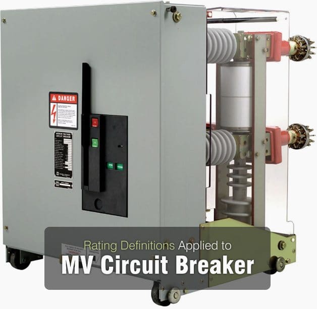
    Rating Definitions Applied to Medium Voltage Fuses (on photo: SOLEFUSE 20kV, via cvmerdekajayateknik.itrademarket.com)

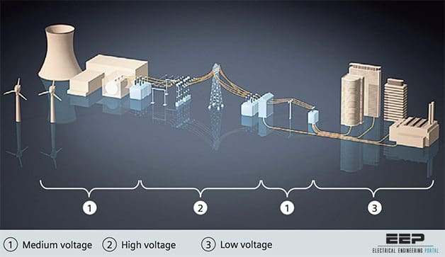
    Greater than 2400V and less than 69kV

    The definition of low voltage fuses is equally applicable to medium voltage fuses. Medium voltage level is defined by standard ANSI C84 as containing standard system voltages from 2400 through 69,000 V, and the high voltage level contains standard system voltages from 115 kV through 230 kV.

    The medium voltage level, strictly, is defined by ANSI C84 as greater than 1000 V and less than 100,000 V. Similarly, the high voltage level is defined as greater than 100,000 V through 230,000 V.

    Strictly-speaking, high voltage fuse standards are used for both medium and high voltage fuses. However the focus of this article will be on medium voltage fuses through 38 kV.

    The following standards apply to medium voltage fuses:

    • IEEE Std. C37.40-2003
    • IEEE Std. C37.41-2000
    • ANSI C37.42-1996
    • ANSI C37.44-1981
    • ANSI C37.46-1981
    • ANSI C37.47-1981
    • IEEE Std. C37.48-1997
    • ANSI C37.53.1-1989

    Generally, medium voltage fuses can be divided into two major categories: Current-limiting and expulsion.


    Current-limiting fuse

    Eaton's CX general purpose current limiting fuses

    Eaton’s CX general purpose current limiting fuses


    Current-limiting fuse is a current-limiting fuse interrupts all available currents its threshold current and below its maximum interrupting rating, limits the clearing time at rated voltage to an interval equal to or less than the first major or symmetrical loop duration, and limits peak let-through current to a value less than the peak current that would be possible with the fuse replaced by a solid conductor of the same impedance. Same basic definition applies to medium voltage fuses.

    Expulsion fuses are defined as follows:

    Expulsion fuse

    A vented fuse in which the expulsion effect of the gases produced by internal arcing, either alone or aided by other mechanisms, results in current interruption.

    EATON's medium voltage expulsion fuses

    EATON’s medium voltage expulsion fuses provide full-range fault protection for both indoor and outdoor, medium voltage distribution systems


    In addition, medium voltage fuses are further classified as power fuses or distribution fuses as follows:


    Power fuse

    Defined by ANSI C37.42-1996 as having dielectric withstand (BIL) strengths at power levels, applied primarily in stations and substations, with mechanical construction basically adapted to station and substation mountings.


    Distribution fuse

    Defined by ANSI C37.42-1996 as having dielectric withstand (BIL) strengths at distribution levels, applied primarily on distribution feeders and circuits, and with operating voltage limits corresponding to distribution voltages.

    These are further subdivided into distribution current limiting fuses and distribution fuse cutouts, as described below.

    Current-limiting fuses interrupt in less than _ cycle when subjected to currents in their current-limiting range. This is an advantage as it limits the peak fault current to a value less than the prospective fault current as described above for low voltage fuses. This provides current-limiting fuses with high interrupting ratings and allows them to protect downstream devices with lower short-circuit ratings in some cases.

    However, the same technologies that combine to give medium voltage current-liming fuses their current-limiting characteristics can also produce thermal issues when the fuses are loaded at lower current levels. For this reason, the following definitions apply to current-limiting fuses.

    Backup current-limiting fuse

    A fuse capable of interrupting all currents from its maximum rated interrupting current down to its rated minimum interrupting current.


    General purpose current-limiting fuse

    A fuse capable of interrupting all currents from the rated interrupting current down to the current that causes melting of the fusible element in no less than 1h.


    Full-range current-limiting fuse

    A fuse capable of interrupting all currents from its rated interrupting current down to the minimum continuous current that causes melting of the fusible elements.

    Due to the limitations of backup and general purpose current limiting fuses, current-limiting power fuses have melting characteristics defined as E or R, defined as follows:

    E-Rating

    The current-responsive element for ratings 100 A or below shall melt in 300 s at an RMS current within the range of 200% to 240% of the continuous-current rating of the fuse unit, refill unit, or use link. The current responsive element for ratings above 100 A shall melt in 600 s at an RMS current within the range of 220% to 264% of the continuous-current rating of the fuse unit, refill unit, or fuse link.

    R-Rating

    The fuse shall melt in the range of 15 s to 35 s at a value of current equal to 100 times the R number. Similarly, distribution current-limiting fuses are defined by given characteristic ratings, one of which is the C rating, defined as follows:

    C-Rating

    The current-responsive element shall melt at 100 s at an RMS current within the range of 170% to 240% of the continuous-current rating of the fuse unit. A typical time-current curve for an E-rated current-limiting power fuse is shown in Figure 1.

    The fuse in Figure 1 is a 125E-rated fuse. Note that the curve starts at approximately 250 A for a minimum melting time of 1000 s.

    Care must be taken with backup and general-purpose current-limiting fuses so that the load current does not to exceed the E- or R-rating of the fuse. Failure to do this can result in the development of a hot-spot and subsequent failure of the fuse and its mounting. For fuses enclosed in equipment, this can have disastrous consequences since failure of the fuse and/or its mounting can lead to an arcing fault in the equipment.

    Note that the boundary of the characteristic, denoting the minimum-melting current, should be further derated to take into account pre-loading of the fuse (consult the fuse manufacturer for details). Note that, as with low voltage fuses, the current-limiting fuse characteristic does not extend below .01 seconds since the fuse would be in its currentlimiting range below this interrupting time.

    Typical E-rated current-limiting power fuse time-current characteristic

    Figure 1 – Typical E-rated current-limiting power fuse time-current characteristic


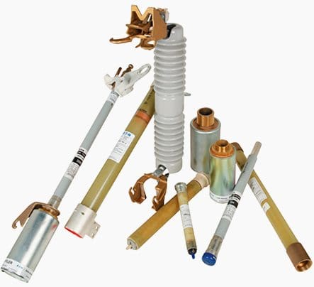
    A current-limiting power fuse consists of a fuse mounting (typically fuse clips) plus the fuse unit itself. These are frequently mounted in metal-enclosed switchgear. A distribution current-limiting fuse may consist of a disconnecting-style holder or clips, plus the fuse unit. Distribution current-limiting fuses may also be provided with under-oil mountings for use with distribution transformers.

    They are frequently used for capacitor protection as well, with clips designed to mount to the capacitor.

    Current-limiting power fuses and mountings

    Figure 2 – Current-limiting power fuses and mountings


    Current-limiting power fuses are typically used for short-circuit protection of instrument transformers, power transformers, and capacitor banks. Table 1 below gives maximum ratings for medium voltage current-limiting power fuses from 2.75 through 38 kV.

    Table 1 – Maximum ratings for current-limiting power fuses 2.75 – 38 kV

    Rated Maximum Voltage (kV)Continuous-Current Ratings (A), MaximumShort-Circuit maximum interrupting ratings (kA RMS symmetrical)
    2.75225,450a,750a, 1350a50.0, 50,0, 40.0, 40.0
    2.75/4.76450a50.0
    5.5225,400,750a,1350a50.0, 62.5, 40.0, 40.0
    8.25125,200a50.0, 50.0
    15.565,100,125a,200a85.0, 50.0, 85.0, 50.0
    25.850,100a35.0, 35.0
    38.035.0, 35.0

    a Parallel Fuses

    During interruption current-limiting fuses produce significant arc voltages. These must be taken into account in selecting equipment. They are typically compared to the BIL level of the equipment, including downstream equipment at the same voltage level. The maximum permissible overvoltages for current-limiting power fuses are shown in Table 2 below:

    Table 2 -Maximum permissible overvoltages for current-limiting power fuses

    Rated Maximum Voltage (kV)Maximum Peak Overvoltages (kV, crest)
    0.5A to 12AOver 12A
    2.8139
    5.52518
    8.33826
    15.06847
    15.57049
    22.011770
    25.811781
    27.012384
    38.0173119

    In practice, the arc voltages for current-limiting fuses generally indicate the use of the smallest available fuse voltage class for the given system voltage, for example, 5.5 kV fuses instead of 8.3kV fuses for a 4160 V system.

    After a fault interruption, in a three-phase set of current-limiting fuses all three fuses will be replaced, even if only one fuse interrupted the fault. This is due to the possibility of damage to the other two fuses due to the fault, which could change their time-current characteristics and make them unsuitable to carry load current without failure.

    Because medium voltage current-limiting fuses interrupt short circuits without the expulsion of gas or flame, they are widely utilized in a variety of applications.

    Medium voltage boric acid expulsion fuses

    Eaton’s BA/DBA Power Fuses are medium voltage boric acid expulsion fuses that offer double protection for circuits and equipment which operate on voltages from 7.2 to 145 kV. They carry the boric acid principle of circuit protection to higher voltage ratings, and at the same time provide at lower cost short-circuit protection for systems of moderate capacity.


    Power expulsion fuses generally consist of an insulating mounting plus a fuse holder which accepts the fuse refills. The fuse holder may be of the disconnecting or non-disconnecting type. Only the refill is replaced when a fuse interrupts an overcurrent, and if only one phase of a three-phase set interrupted the fault only that fuse need be replaced.

    Power expulsion fuses are typically used in substations and enclosed equipment.

    Distribution expulsion fuses are generally distribution fuse cutouts, which are adapted to pole or cross arm mounting. They consist of the fuse holder and refill unit. The fuse holder is usually of the disconnecting type. These are typically used as pole-mounted fuses on utility distribution systems.

    Expulsion fuses use the liberation of de-ionizing gasses to interrupt overcurrents. Boric acid is typically used as the interrupting medium for power expulsion fuses and bone fiber is typically used for distribution fuse cutouts. When an expulsion fuse interrupts an overcurrent the interrupting medium liberates de-ionizing gas, interrupting the overcurrent.

    The exhaust gasses are then emitted from the fuse, accompanied by noise. The exhaust gasses for a boric acid fuse may condensed by an exhaust control device (commonly called an exhaust filter, silencer, or snuffler).

    Unlike current-limiting fuses, expulsion-type fuses interrupt high overcurrents at natural current zeros. They are therefore non-current-limiting, and as a result typically have lower interrupting ratings than current-limiting fuses.

    Table 3 below shows the maximum continuous current and short-circuit interrupting ratings for refill-type boric-acid expulsion-type power fuses. Because expulsion-type fuses are non-current-limiting, they do not produce the significant arc voltages that current-limiting fuses produce, and thus it is permissible to use a fuse with a larger voltage class than the system, for example, a 14.4 kV-rated fuse on a 4160 V system. This makes expulsion-type fuses particularly useful on systems which may be upgraded in the future to a higher voltage.

    Littelfuse's medium voltage fuses, E- and R-rating

    Littelfuse’s medium voltage fuses, E- and R-rating


    However, the lower interrupting ratings of expulsion-type fuses are often an issue vs. current-limiting fuses in light of the fact that the largest expulsion-type fuse interrupting ratings require larger physical dimensions which cannot always be easily accommodated in enclosed equipment. Further, in some cases the expulsion-type fuses prohibit some spacesaving mounting configurations in enclosed equipment that are available with current-limiting fuses.

    Table 3 – Maximum continuous current and short circuit interrupting ratings for refill type boric-acid expulsion-type power fuses

    Rated Maximum Voltage (kV)Continuous-Current Ratings (A),
    maximum
    Short-Circuit maximum
    interrupting ratings
    (kA, RMS symmetrical)
    2.8200,400,720a19.0, 37.5, 37.5
    4.8200,400,720a19.0, 37.5, 37.5
    5.5200,400,720a19.0, 37.5, 37.5
    8.3200,400,720a16.6, 29.4, 29.4
    14.4200,400,720a14.4, 29.4, 29.4
    15.5200,400,720a14.4, 34.0, 29.4
    17.0200,400,720a14.4, 34.0, 25.0
    25.8200,300,540a10.5, 21.0, 21.0
    27.0200,30012.5, 20.0
    38.0200,300,540a8.45, 17.5, 16.8

    a Parallel Fuses

    E-ratings are used for power expulsion fuses. A typical time-current characteristic for a 125E boric-acid fuse is given in Figure 2 below.

    Typical boric acid power expulsion fuse time-current characteristic

    Figure 2 – Typical boric acid power expulsion fuse time-current characteristic


    Note that the characteristic extends to the available fault current (in this case, 29.4 kA), unlike that of the current-limiting fuse. It is common practice to treat these as current-limiting fuses so far as the E-rating is concerned, i.e., the maximum load current is usually kept below the E-rating. However, the boric-acid fuse is not subject to damage when loaded above its E-rating, and they are often referred to in the industry as non-damageable due to this fact.

    When applying medium voltage fuses, the voltage rating and the interrupting rating are of importance.

    The maximum line-to-line voltage of the system should not exceed the fuse voltage rating. The published interrupting rating for power fuses is typically for a test X/R ratio of 15, and for distribution fuses the test X/R ratio is typically 8; the fuse manufacturer should be consulted for derating factors for X/R ratios above these values.

    The manufacturer should also be consulted if the test X/R is in doubt.

    Medium voltage fuses provide economical short-circuit protection when applied within their ratings, particularly for transformers, cables, and capacitors. For more sophisticated protection at the medium voltage level, other means must be employed.

    Reference: System Protection – Bill Brown, P.E., Square D Engineering Services

    Viewing all 138 articles
    Browse latest View live