34 Questions And Answers To Break the Myth About SF6 Gas In Electrical Equipment
Miracle gas or not?
There are many published discussions and reports on various aspects of SF6 gas (sulphur hexafluoride) usage in electrical equipment. Most of them are based on facts and researches, but some are not. Let’s try to answer the 34 questions and break the myth about this ‘miracle’ gas.
Note that most of answers are based on CAPIEL (Coordinating Committee for the Associations of Manufacturers of Industrial Electrical Switchgear and Controlgear in the European Union) researches and related IEC standards as well.
1. Where is SF6 used?
The following applications are known. For some of these most probably you haven’t heard of.
- For sound insulation in windows,
- In vehicle tyres,
- For magnesium casting in the automotive industry,
- As insulating and arc extinguishing medium in electric power equipment,
- For manufacturing of semi-conductors,
- In tandem-particle accelerators,
- In electron microscopes,
- As tracer-gas in mining,
- In x-ray material examination equipment,
- As purification and protection gas for aluminium and magnesium casting,
- In sport shoes,
- Medical examinations,
- In military aircraft radar systems and other military applications.
2. Is SF6 a health hazard?
Pure SF6 is physiologically completely harmless for humans and animals. It’s even used in medical diagnostic. Due to its weight it might displace the oxygen in the air, if large quantities are concentrating in deeper and non ventilated places.
3. Is SF6 harmful for the environment?
It has no ecotoxic potential, it does not deplete ozone. Due to its high global warming potential of 22.200 (*) it may contribute to the man made greenhouse-effect, if it is released into the atmosphere. However in electrical switchgear the SF6 gas is always used in gas-tight compartments, greatly minimising leakage. This make the real impact on greenhouse effect negligible.
(*) According to the 3rd Assessment Report of UNFCCC. Previous accepted value was 23.900
4. What is the overall contribution of SF6 used in the electrical equipment to the greenhouse effect?
Less than 0,1 % ( see CAPIEL) and CIGRE). In an Ecofys study the contribution to the greenhouse effect in Europe is estimated to 0.05 % (*).
(*) ECOFYS, Sina Wartmann, Dr. Jochen Harnisch, June 2005, “Reductions of SF6 Emissions from High and Medium Voltage Equipment in Europe”
5. How wide is the use of SF6 in transmission and distribution switchgear applications ?
SF6 insulated switchgear is currently used world-wide. It is estimated that an average of about 80 % of HV equipment manufactured now has an SF6 content.
6. Why is SF6 used in electric power equipment?
Because of its outstanding electrical, physical and chemical properties enabling significant benefits for the electricity supply network:
- It insulates 2.5 times better than air (N2),
- Over 100 times better arc quenching capability than air (N2), and
- Better heat dissipation than air;
In addition to this, LCA studies have proven that the use of SF6 technology in the electrical distribution switchgear equipment results in lower overall direct and indirect environmental impacts compared to air-insulated switchyards (*)
(*) Solvay Germany, 1999: Urban power supply using SF6 technology, Life cycle assessment on behalf of ABB, PreussenElektra Netz, RWE Energie, Siemens, Solvay Fluor und Derivate
7. What are the benefits of high and medium voltage SF6-switchgear?
There is a significant number of benefits, as follows:
Local operator safety
- SF6-insulated switchgear makes a substantial contribution to reduce the accident risk.
- The total enclosure of all live parts in earthed metal enclosures provides immanent protection against electric shock and minimises the risks associated with human errors
- The high-grade switchgear remains hermetically sealed for its whole service life.
Very high operational reliability
- It offers a great operational reliability because inside the enclosed gas compartments the primary conductors have complete protection against all external effects.
- The minimal use of synthetics reduces the fire load.
- The SF6 insulation ensures complete freedom from oxidation for the contacts and screwed joints, which means that there is no gradual reduction in the current carrying capacity of the equipment as it ages.
- There is no reduction in insulation capacity due to external factors.
Important contribution to the security of supply
Total enclosure also means that the equipment is almost completely independent from the environment. SF6 insulated switchgear can also be used under difficult climatic conditions, for example:
- In humid areas with frequent condensations from temperature changes, and even in places with flooding potential.
- Where the reliability of the insulation might otherwise suffer from contamination, e.g. dust from industry or agriculture or saline deposits in coastal areas. Gas- insulated switchgear completely eliminates this possibility throughout the whole service life of an installation
- In contrast to air insulation, whose insulating capacity reduces with increasing altitude, SF6-insulated switchgear retains its full insulating capacity regardless of height above sea level. So larger and more costly special designs, or equipment with higher insulation ratings – and therefore more costly – are avoided
Small space requirement
- Due to the high dielectric strength of the gas, the switchgear is compact with space requirements minimised.
- The excellent safety and low space requirement of SF6 switchgear allows it to be sited directly in conurbations and close to load centres, such as city centres, industrial manufacturing plants and commercial areas.
- Therefore, this fulfils one of the basic essentials of power distribution, namely that substations should be placed as close as possible to load centres in order to keep transmission losses to a minimum, to conserve resources and to minimise costs.
- Major savings in building, land and transport costs can be achieved throughout the whole process chain.
- In several cases SF6 switchgear is the only possible solution: for wind power plants (offshore), in caverns, for large generator circuit-breakers, and for extensions of existing installations.
- This often allows existing buildings use to be extended where switchgear replacement or extension to meet load growth is needed.
Excellent economical and ecological features
- Distinct economic benefits come from:
- The long service life
- Minimal maintenance expenditure thanks to maintenance-free, gas-tight enclosures
- Reduced costs for land, buildings, transport and commissioning
- Maximum operational reliability as a prerequisite for the remote control and automation of power networks
- Ecological and economic benefits arise from:
- Minimum transmission losses as a result of placing equipment close to load centres.
- Reduced primary energy consumption and emissions contribute to economically optimised power supply systems.
- And the long service life of SF6 switchgear also contributes to the conservation of resources.
- Aesthetic and ecological benefits for rural and city landscapes:
- Because SF6 installations are compact, need minimum maintenance, have extraordinarily high availability and are independent from climatic impacts. They offer not only major ecological and economic advantages but can also be integrated seamlessly in any landscape or architecture of towns, cities or countryside
- Reclamation of areas previously taken up by conventional substations.
8. Is there any alternative to SF6 in switchgear for high and medium voltage?
From the LCA point of view no technically and economically viable alternative exists with an equivalent set of properties described above and the same degree of safety and reliability.
”A combination of extraordinary electrical, physical, chemical and thermal properties makes SF6 a unique and indispensable material in electric power equipment for which there is no functionally equivalent substitute.” (Quotation from a CIGRE3 Report) (*)
(*) CIGRE: International Council on Large Electric Systems
9. What are the different applications in electrical power equipment using SF6?
These are the most common applications where SF6 is used:
- GIS (Gas Insulated Switchgear for medium and high voltage),
- CBs (Circuit Breaker),
- Power transformers,
- VT (Voltage Transformer),
- CT (Current transformer),
- RMU (Ring Main Unit),
- Assemblies of HV devices and GIL (Gas insulated lines),
- Capacitors etc.
10. What is the difference between high-voltage (HV) and medium- voltage (MV) GIS regarding SF6?
Basically there is no difference as both applications use the SF6 in gas-tight compartments with negligible leakage rates. In general the MV (up to 52 kV) use pressures close to atmospheric pressure in sealed pressure systems. Low pressure and small size result in little gas quantities of only some kg. The leakage rate is extremely low, less than 0.1 % per year.
11. What are the main commitments of the voluntary actions/agreements of manufacturers and users concerning SF6 handling?
Both, switchgear manufacturers and users are committed to a continuous improvement in reduction of emission rates as well as monitoring and annual reporting.
12. How is the effectiveness of voluntary actions verified?
The production processes of MV and HV switchgear in Western Europe have been improved so to reduce the specific emission rates of about 2/3 from1995 to 2003. Ecofys (*) determined for the same period an emission reduction of 40 %.
(*) ECOFYS, Sina Wartmann, Dr. Jochen Harnisch, June 2005, “Reductions of SF6 Emissions from High and Medium Voltage Equipment in Europe”
13. What are the user’s obligations for monitoring SF6 data of medium voltage switchgear?
As far as sealed pressure systems (sealed for life) are concerned the users do not normally need to either monitor or report emissions.
Therefore they only have to assure that the disposal and the end of life is carried out by a qualified entity, in accordance with available national rules.
14. How is the proper end-of-life treatment of SF6-switchgear ensured?
Following internationally acknowledged instructions (i.e. according to IEC 601634, CIGRE 2003 SF6 Recycling Guide).
Cant see this video? Click here to watch it on Youtube.
15. What are the user’s obligations when taking SF6-switchgear out of service?
To make sure that the SF6 is handled by a qualified entity or by qualified personnel according to IEC 61634 subclause 4.3.1. and according to IEC 60480 subclause 10.3.1.
16. How is used SF6-gas treated or disposed?
It is normally re-used after proper filtering. In some special cases disposal of the gas is necessary.
17. In some European countries bans on SF6-switchgear have been proposed. Where are legal bans implemented?
There are no legal bans implemented. In political discussions reduced use of SF6 in some applications was proposed which are not related to the electrical industry.
In the past some proposals of this kind concerning electrical switchgear came up due to insufficient knowledge on how the electrical industry is using SF6. Once this was clarified and the benefits given by this technology were explained, the proposals were withdrawn.
18. Can we use vacuum as insulation medium?
Vacuum technology is already in use for switching purposes in the MV range. In the case of a small volume, a vacuum can be relatively easy maintained, which is essential to assure the performance of the switching device.
19. How can the user supervise the SF6 quality?
The sealed for life MV equipment does not require SF6 quality checks. For other HV equipment Annex B of IEC 60480 describes different methods of analysis applicable for closed pressure systems (on-site and in laboratory).
20. What about ageing process of SF6 gas? Is replenishment of gas needed after approximately 20 years?
It is generally not necessary because the gas quality than is in line with the values given in IEC 60480 Table 2 “Maximum acceptable impurity levels” (applicable for closed pressure systems). For MV sealed for life equipment no replenishment is necessary, because of the unique qualities of SF6 under normal operating conditions no degradation occurs.
21. How much SF6 (quantified in kg) can escape due to “normal” leakage?
This depends on the filling quantity, which depends on the rating and design of the equipment (volume and pressure). For HV switchgear the emission factor ranges from about 0.1% per year to 0,5% (0,5% per year is the maximum acceptable leakage rate according to IEC 62271-203)
For sealed for life MV equipment a range below 0,1 % per year is common. For example, a 3 kg filling quantity (RMU) results in a calculated loss of 3 g per year.
22. How high is the MAC (Maximum allowable working environment concentration) for pure SF6 in the substation and how hazardous is pure SF6?
It is generally recommended that the maximum concentration of SF6 in the working environment should be kept lower than 1000 μl/l (*). This is the value accepted for a full time (8 h/day, 5 day/week) work schedule. This value is not related to toxicity, but an established limit for all non-toxic gases which are not normally present in the atmosphere.
(*) TRGS 900, Technische Regeln für Gefahrstoffe
23. What decomposition products are created in the case of internal arc faults, and in what quantities?
Gaseous and dusty by-products will be generated. See IEC 60480, Table 1 and/or CIGRE Report Electra 1991 (“Handling of SF6 and its decomposition products in GIS”, Table 2 “Rough characterisation of the major decomposition products resulting from different sources”).
The decomposition products depend on the type of equipment and its service history; the quantities depend on energy (voltage, current, time) and the type of the equipment.
24. How hazardous are the decomposition products?
See IEC 61634, Annex C: “Release of SF6 from switchgear and control gear – potential effects on health”.
Calculations show that, in practice, only in case of an internal arc with a massive emission of heavily arced gas a real hazard is created. Evacuation and ventilation is therefore compulsory in such an event.
25. What has to be done after an arc fault in the switchgear?
In such accidental cases caution must be taken. If the encapsulation has been damaged some compounds with toxic characteristics may be present, generated not only from decomposition of SF6 but also from other sources (e.g. burning paintings, vapours of copper, etc) can be present.
Therefore, in all cases, evacuation of the switchgear room is the first measure to be taken irrespective the switchgear contains SF6 or not. See IEC 61634 sub-clause 5.3: “Abnormal release due to internal fault”.
26. Does a (passive or active) ventilation system have to be installed in the switchgear room or cable basement?
Buildings containing SF6-filled indoor equipment should be provided with ventilation; natural ventilation would normally be adequate to prevent the accumulation of SF6 released due to leakage (see IEC 61634, sub-clause 3.4: “Safety of personnel” and IEC 61936-1). Type and extent of required measures depend upon location of the room, the accessibility, and the ratio of gas to room volume.
27. What do I have to do when a GIS installation is damaged?
For example hole drilled in encapsulation or transport damage such as a panel dropped and cast resin broken) and SF6 escapes or when my GIS develops an abnormal leak?
Appropriate corrective action should be to deal with the leakage. If the equipment is in service and the leakage is high, it must be de-energised, in accordance with the organisation’s operational procedures. Loss of gas must be minimised by following the organisation’s procedures and using the services/recommendations of the manufacturer or qualified service organisation as appropriate.
The technical integrity of the equipment will need to be verified after such an occurrence and appropriate corrective actions taken by authorised personnel before refilling of equipment or placing in service.
28. Under which conditions needs SF6 gas in gas-insulated switchgear to be replaced?
Which are the parameters to be checked e.g. (concentration, dew point, decomposition products) and what are the related acceptable limits?
Normally the gas remains until disassembly. During a maintenance operation requiring the evacuation of the gas, it should be analysed. Guidance on how to proceed then is given in IEC 60480.
29. How do I evacuate and fill the system?
See IEC 61634, CIGRE Report 2004 (“Practical SF6 handling instructions”). Please, refer also to the instruction manual of your equipment.
30. How much SF6 gas is in my switchgear? Where do I find this information?
On the nameplate or in the operating manual. For older equipment please ask your manufacturer.
31. Does SF6 have to be disposed of when moist?
No, it is possible to dry the gas; moisture can be reduced to acceptable levels by adsorption; material such as alumina, soda lime, molecular sieves or mixtures thereof are suitable for this purpose (see also IEC 61634, Annex B.3: “Measures for the removal of SF6 decomposition products”). Maximum tolerable moisture levels for re-use can be taken from IEC 60480, Annex A.
32. What do I have to do when I came in contact with decomposed SF6?
See IEC 61634, Annex E: “General safety recommendations, equipment for personal protection and first aid”. Normally only trained and qualified personnel should deal with this and hence be aware of the necessary precautions and actions.
IEC 61634, Annex E: General safety recommendations, equipment for personal protection and first aid
For medium-voltage switchgear and controlgear using sealed pressure systems, the contents of this annex are applicable only during end-of-life treatment or in the very unlikely event of an abnormal release. For other types of equipment, information in this annex is provided for use in situations where workers have to make contact with SF6 decomposition products.
Such situations include:
- Maintenance or any other activity involving opening the SF6-filled enclosures of equipment which has been in service;
- Restorative activity after an internal fault or external fire provoking opening of the enclosure.
Experience over more than 25 years in working environments where contaminated gas is handled regularly has shown that personnel are unlikely to suffer adverse effects to their health, as long as they are suitably trained and equipped as indicated in this report and as recommended in the manufacturers’ instructions.
33. What environmental and safety at work aspects have to be taken into account?
See IEC 61634 [8], clause 4: “Handling of used SF6″.
The need to handle used SF6 arises where:
- Topping up of the SF6 in closed pressure systems is carried out;
- The gas has to be removed from an enclosure to allow maintenance, repair or exten-sion to be carried out;
- The gas has been wholly or partially expelled due to an abnormal release;
- The gas has to be removed at the end of the life of an item of equipment;
- Samples of the gas must be obtained or the gas pressure measured through tempo-rary connection of measuring apparatus.
Situations 1 and 1 arise mainly with respect to high-voltage equipment and may arise with medium-voltage GIS equipment in particular if it is required to add further equipment to an existing switchboard. They do not arise with equipment using sealed pressure systems.
34. What has to be observed for cleaning of the switchgear room after an internal fault with emission of decomposed gas?
See IEC 61634, sub-clause 5.3/5.3.3:
Abnormal release due to internal fault (Indoor installations”, and national requirements.)
An internal fault occurs when abnormal arcing is initiated inside a switchgear and controlgear enclosure.
In certain types of equipment, particularly metal-enclosed medium-voltage switchboards, air insulation is used for the busbars between cubicles and around cable connections and SF6 is present only within switching chambers. In this case an internal fault could occur within the switchboard but outside the switching chamber, so that no SF6 is released.
An internal fault is a very rare occurrence but cannot be completely disregarded.
- A defect in the insulation system;
- A mechanical defect leading to a disturbance of the electric field distribution inside the equipment;
- The mal-operation of part of a switching device due to faulty assembly, components or malfunction or misuse of interlocks.
An internal fault will cause an increase of pressure inside the enclosure, the effects of which will depend upon circumstances. The pressure rise is caused by the transfer of the electrical energy from the arc into the gas. The increase in pressure will depend upon the value of the arc current, the arc voltage, the arc duration and the volume of the enclosure in which the arc has developed.
Following an internal fault leading to pressure relief or enclosure burn-through, the SF6 and much of any solid decomposition products (powders) will have been expelled from the SF6 enclosure.
References:
- CAPIEL (Coordinating Committee for the Associations of Manufacturers of Industrial Electrical Switchgear and Controlgear in the European Union) – Frequently asked Questions (FAQ) and Answers on SF6
- IEC 61634 High-voltage switchgear and controlgear – Use and handling of sulphur hexafluoride (SF6) in high-voltage switchgear and controlgear
- IEC 60480 Guidelines for the checking and treatment of sulphur hexafluoride (SF6) taken from electrical equipment and specification for its re-use


")


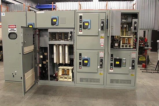
 Switchgears (on photo\" Eaton Cutler Hammer Magnum DS Switchgear Inspection, and Transformer Testing)")


")
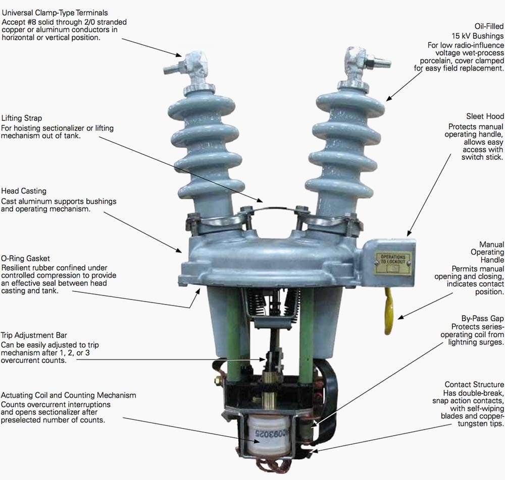
 to open fuse switch disconnector")


 and primary current (IP)")